
Hydraulic movable dam operating system

A technology of operating system and hydraulic system, which is applied in water conservancy projects, sea area projects, coastline protection, etc., and can solve problems such as short life, high maintenance costs, and manual cleaning.

Inactive Publication Date: 2013-08-14
SUZHOU ZHENGXINTAI AUTOMATION SYST
View PDF5 Cites 7 Cited by
  • Summary
  • Abstract
  • Description
  • Claims
  • Application Information

AI Technical Summary

Problems solved by technology

[0002] The main applications in water conservancy systems include ram dams, rubber dams, water conservancy automatic flip dams and hydraulic lifting dams. Because ram dams are made of steel, the cost of starting equipment is large and the maintenance costs are high; rubber dams are the first in the United States. The mature technology has the advantages of low production cost and convenient maintenance in the later stage, but it has the problems of easy damage, low lifting efficiency and short life; the hydraulic automatic flap dam, as an advanced technology in Japan, also has the advantages of convenient maintenance in the later stage, but When applied to complex river systems, it is easy to be stuck by sand, stones, trees, bamboo and other silts in the river, so that the dam surface cannot be completely closed, and it must be cleaned manually, which is inconvenient to use; the hydraulic dam solves the above shortcomings and is easy to use , suitable for water conservancy construction of any complex river course, but due to the large load bearing of the overall dam surface during water storage, the current driving force of the dam surface is not ideal

Method used


Image

  • Hydraulic movable dam operating system
  • Hydraulic movable dam operating system
  • Hydraulic movable dam operating system

Examples


Embodiment Construction

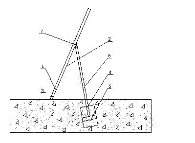
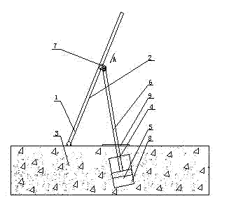
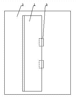
[0025] figure 1 , figure 2 , image 3 with Figure 4 The hydraulic movable dam operation system shown includes dam surface 1, dam surface backwater surface 2, horizontal foundation 3, main hydraulic system 4, hydraulic cylinder 5, hydraulic cylinder extension rod 6, lug structure 7, hydraulic cylinder body 8, Steel plate glue sealing structure 9, spherical structure 10, through hole 11, assembly hole 12, pin shaft 13, spherical groove 14, axial locking hole 15, small pin shaft 16.

[0026] The hydraulic movable dam operating system of the present invention mainly includes: a dam surface 1 and a main hydraulic system 4. When setting the dam surface, ensure that the back water surface of the dam surface forms an acute angle with the horizontal foundation, and its bottom edge is hinged on the support column on the horizontal foundation. The main hydraulic system 4 is mainly a hydraulic cylinder 5 and a hydraulic circuit arranged on the horizontal foundation 3 of the backwate...


PUM


Abstract

The invention discloses a hydraulic movable dam operating system which is characterized by comprising a dam face and two main hydraulic systems. An acute angle is formed between the dam face and a horizontal foundation, and the bottom edge of the dam face is hinged on props of the horizontal foundation; each main hydraulic system mainly comprises a hydraulic cylinder and a hydraulic circuit which are arranged on the horizontal foundation and a downstream face of the dam face, and an extension bar of the hydraulic cylinder is oblique relative to the downstream face of the dam face, so that a herringbone is formed; and the hydraulic circuits mainly comprise the hydraulic cylinders, reversing valves, hydraulic pumps and hydraulic oil pipes, and the hydraulic oil pipes are laid in the horizontal foundation. The hydraulic movable dam operating system has the advantages that the two main hydraulic systems which enable the herringbones to be formed between the dam face and the downstream face of the dam face drive the dam face, and are bilaterally symmetrically arranged on the downstream face of the dam face in order to guarantee reasonable stress, and driving power is provided for the dam face.

Description

technical field [0001] The invention relates to a hydraulic movable dam operating system, in particular to a hydraulic movable dam operating system with simple structure, good mechanical performance, waterproof and anti-freezing. Background technique [0002] The main applications in water conservancy systems include ram dams, rubber dams, water conservancy automatic flip dams and hydraulic lifting dams. Because ram dams are made of steel, the cost of starting equipment is large and the maintenance costs are high; rubber dams are the first in the United States. The mature technology has the advantages of low production cost and convenient maintenance in the later stage, but it has the problems of easy damage, low lifting efficiency and short life; the hydraulic automatic flap dam, as an advanced technology in Japan, also has the advantages of convenient maintenance in the later stage, but When applied to complex river systems, it is easy to be stuck by sand, stones, trees, b...

Claims


Application Information

Patent Timeline
Patent Type & Authority Applications(China)
IPC IPC(8): E02B7/44
Inventor 赵升琼
Owner SUZHOU ZHENGXINTAI AUTOMATION SYST
Learn More