Electrical control rectifying valve of hydraulic electric feed energy shock absorber

A technology of shock absorbers and rectifier valves, which is applied in the direction of fluid pressure actuators, servo motor components, mechanical equipment, etc., and can solve problems such as system malfunction, difficult maintenance and replacement, hydraulic energy loss, etc., to avoid energy loss , easy maintenance, and the effect of reducing the possibility

Inactive Publication Date: 2013-08-14
WUHAN UNIV OF TECH
View PDF10 Cites 17 Cited by
  • Summary
  • Abstract
  • Description
  • Claims
  • Application Information

AI Technical Summary

Problems solved by technology

However, its rectifier bridge is composed of four mechanical one-way valves, and it is very easy to fail due to excessive impact at the critical point of the piston reversing; the rectifier bridge is composed of four one-way valves, and the failure of any one-way valve will cause system failure. It cannot work normally, and the failure probability of each check valve is the same, so it is not easy to repair and replace; in addition, the mechanical check valve needs to push the spring open by pressure, which will inevitably cause a certain loss of hydraulic energy

Method used


Image

  • Electrical control rectifying valve of hydraulic electric feed energy shock absorber
  • Electrical control rectifying valve of hydraulic electric feed energy shock absorber
  • Electrical control rectifying valve of hydraulic electric feed energy shock absorber

Examples


Embodiment Construction

[0035] The present invention will be further described below in conjunction with the embodiments and accompanying drawings, but the present invention is not limited.

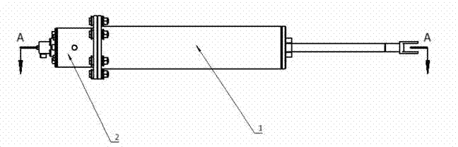
[0036]The purpose of the electronically controlled rectifier valve provided by the present invention is: it is specially designed for the hydraulic-electric energy-feeding shock absorber based on the integration of "mechanical-electric-hydraulic", and is used to rely on the upper and lower chamber pressure signals collected by the sensor according to the working requirements of the shock absorber. , to judge the flow characteristics of the liquid in the shock absorber, and drive the solenoid valve control valve to switch between the two working conditions through the control algorithm, rectify the flow direction of the liquid, and ensure that the flow direction of the output port is consistent.

[0037] The electronically controlled rectifying valve of the hydraulic electric energy feed shock absorber provided by...


PUM


Abstract

The invention provides an electrical control rectifying valve of a hydraulic electric feed energy shock absorber. The electrical control rectifying valve comprises a hydraulic cylinder, a rectifying valve, pressure sensors of an upper cavity and a lower cavity of a piston, a control unit and guide wires. The working principle of the electrical control rectifying valve includes that energy generated from vibration of the hydraulic cylinder is converted into hydraulic energy, the hydraulic energy is passed in a system via liquid flows, the flowing direction of liquid at the front end of the rectifying valve is judged by utilizing the control unit to compare pressure signals acquired by the upper-cavity pressure sensor and the lower-cavity pressure cavity, the spool position of the rectifying valve is controlled via an electromagnetic valve, liquid flows from a shock absorber cylinder are rectified, the liquid flow rectified is capable of driving a hydraulic motor to work towards another direction to drive a generator to generate power, and thereby vibrating energy is converted into electric energy to be recovered. The electrical control rectifying valve is specially designed for the hydraulic electric feed energy shock absorber, rectifying is realized via controlling an algorithm, over-impact to a spool when the liquid flows reverse is avoided, service life of the valve is prolonged, and meanwhile, a reversing time of the spool is precisely controlled, and the hydraulic energy is fully utilized to recover the vibrating energy.

Description

technical field [0001] The invention relates to a valve, in particular to an electronically controlled rectifying valve for a hydraulic-electric energy-feed shock absorber used for energy recovery and damping force adjustment. Background technique [0002] During the driving process of the vehicle, due to the bumps of the road surface and during the acceleration, deceleration and steering of the vehicle, the sprung mass and the unsprung mass will generate relative vibrations. The shock absorber is used to provide damping force for the suspension and absorb the energy generated by the vibration. It is converted into other energy and dissipated to achieve vibration attenuation. If this part of the vibration energy can be recovered, it will have positive significance for reducing the energy consumption of the vehicle. [0003] As we all know, the traditional shock absorber performs reciprocating linear motion under the excitation of the road surface. The piston of the shock ab...

Claims


Application Information

Patent Timeline
Patent Type & Authority Applications(China)
IPC IPC(8): F15B13/02
Inventor 周泉方志刚杨波龚边夏欢王硕车堃储潘奇张斌韬
Owner WUHAN UNIV OF TECH
Why Eureka
Try Eureka