Small liquefied natural gas vaporizer

A technology of liquefied natural gas and vaporizer, applied in the direction of heat exchanger type, indirect heat exchanger, fixed tubular conduit assembly, etc., can solve the problems of large heat source fluid flow rate, affecting vaporization efficiency, increasing intermediate medium shell, etc. High thermal efficiency, wide application range, and low cooling energy loss

Active Publication Date: 2013-08-14
CIMC VEHICLES SHANDONG
View PDF6 Cites 20 Cited by
  • Summary
  • Abstract
  • Description
  • Claims
  • Application Information

AI Technical Summary

Problems solved by technology

[0005] Disadvantages: The cold energy generated during the vaporization process is not recycled, and the seawater is easy to freeze, which affects the vaporization efficiency;
[0008] Disadvantages: It is necessary to select a matching intermediate medium, increase the intermediate medium shell, and have a complex structure;
[0011] Disadvantages:

Method used


Image

  • Small liquefied natural gas vaporizer
  • Small liquefied natural gas vaporizer

Examples


Embodiment 1

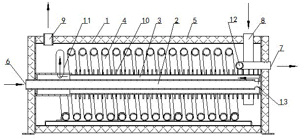
[0027] as attached figure 1 As shown, the small liquefied natural gas vaporizer of the present invention is mainly composed of a shell 1 , an inner tube 2 , a sleeve 3 and a coil 4 .

[0028] The shell 1 with the insulation layer 5 is provided with an LNG inlet 6 , an NG outlet 7 , a refrigerant inlet 8 and a refrigerant outlet 9 . The inner tube 2 , the sleeve tube 3 and the winding tube 4 are all fixed in the casing 1 .

[0029] The inner tube 2 is fixed in the middle of the housing 1 , and the casing 3 and the winding tube 4 are sequentially sleeved on the outside of the inner tube 2 . A heat exchange fin 10 is fixed on the outer wall of the casing 3 .

[0030] The outer end of the inner pipe 2 is connected to the LNG inlet 6 , and its insertion end 13 communicates with the casing 3 . The end of the casing 3 away from the insertion end 13 of the inner tube communicates with the medium inlet end 11 of the winding tube 4 . The medium output end 12 of the winding pipe 4 co...

Embodiment 2

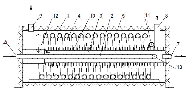
[0033] as attached figure 2 As shown, the small liquefied natural gas vaporizer of the present invention is mainly composed of a shell 1 , an inner tube 2 , a sleeve 3 and a coil 4 .

[0034] The shell 1 with the insulation layer 5 is provided with an LNG inlet 6 , an NG outlet 7 , a refrigerant inlet 8 and a refrigerant outlet 9 . The inner tube 2 , the sleeve tube 3 and the winding tube 4 are all fixed in the casing 1 .

[0035] The inner tube 2 is fixed in the middle of the housing 1 , and the casing 3 and the winding tube 4 are sequentially sleeved on the outside of the inner tube 2 . A heat exchange fin 10 is fixed on the outer wall of the casing 3 .

[0036] The outer end of the inner pipe 2 is connected to the LNG inlet 6 , and its insertion end 13 communicates with the medium inlet end 11 of the winding pipe 4 . The medium output end 12 of the winding tube 4 communicates with the end of the casing 3 away from the insertion end 13 of the inner tube. One end of the ...


PUM


Abstract

The invention relates to the technical field of heat exchangers, and particularly provides a small liquefied natural gas (LNG) vaporizer which structurally comprises a shell. An LNG inlet, an NG (natural gas) outlet, a refrigerant inlet and a refrigerant outlet are arranged on the shell, and an inner pipe which is communicated with the LNG inlet is arranged in the shell. The small liquefied natural gas vaporizer is characterized in that a sleeve is arranged on the outer side of the inner pipe, and an inserting end of the inner pipe is communicated with the NG outlet via the sleeve. The small liquefied natural gas vaporizer has the advantages that in LNG vaporization and cold energy storage procedures, the small liquefied natural gas vaporizer can prevent refrigerants from freezing and is high in heat efficiency, is suitable for various LNG cold energy utilization places, and is particularly suitable for air conditioners of LNG automobiles or refrigeration for LNG refrigerator cars, and the like.

Description

technical field [0001] The invention relates to the technical field of heat exchangers, and specifically provides a small liquefied natural gas vaporizer. Background technique [0002] The vaporizer is an indispensable and important component in the application process of liquefied natural gas (LNG). The following types of vaporizers are mainly included in the prior art: [0003] (1) Open frame carburetor [0004] The vaporizer with seawater as the heat source fluid is a large-scale LNG vaporization device for base load. The basic unit of the vaporizer is the heat transfer tube, which is composed of several heat transfer tubes arranged in a plate shape, and the two ends are welded by the gas collector or liquid collector to form a plate-shaped tube bundle, and then the vaporizer is composed of several plate-shaped tube bundles. There is a seawater spraying device on the top of the carburetor, and the seawater is sprayed on the outer surface of the plate-shaped tube bundle...

Claims


Application Information

Patent Timeline
IPC IPC(8): F28D7/00
Inventor 李道彭梁仲文李红兵苏念张瑞成周可杜
Owner CIMC VEHICLES SHANDONG
Why Eureka
Try Eureka