Antenna directional pattern testing method based on spherical surface near-field scanning extrapolation

An antenna pattern and testing method technology, applied to the antenna radiation pattern and other directions, can solve the problems of difficult to obtain the antenna far-field three-dimensional pattern, easy to be subject to external interference, high cost and other problems, so as to achieve accurate analysis of antenna performance and intuitive analysis. Antenna performance, effect of reducing test distance

Inactive Publication Date: 2013-08-14
NORTHWESTERN POLYTECHNICAL UNIV
View PDF7 Cites 23 Cited by
  • Summary
  • Abstract
  • Description
  • Claims
  • Application Information

AI Technical Summary

Problems solved by technology

Generally, when the test frequency is high and the physical size of the antenna is large, it is difficult for the ordinary indoor test site to meet the test conditions, and an outfield test is required. However, in addition to the high cost of the outfield test, due to its long distance and environmental Openness makes the test extremely vulnerable to external interference and is not conducive to confidentiality
However, the current engineering test only analyzes the performance of the antenna by drawing the E-plane and H-plane of the antenna, and it is difficult to obtain the three-dimensional pattern of the far field of the antenna.
[0003] If the near-field test is used, the high end of the frequency is 3GHz, the wavelength λ=10cm, and the length, width, and height of the antenna are 1m. The distance R that satisfies the near-field condition can be calculated by the following formula, namely Under this condition, due to the high height of the antenna itself, the cylindrical wave cannot be approximated as a plane wave, and the measured data will have a large error

Method used


Image

  • Antenna directional pattern testing method based on spherical surface near-field scanning extrapolation
  • Antenna directional pattern testing method based on spherical surface near-field scanning extrapolation
  • Antenna directional pattern testing method based on spherical surface near-field scanning extrapolation

Examples


Embodiment Construction

[0018] Now in conjunction with embodiment, accompanying drawing, the present invention will be further described:

[0019] A near-field pattern test is performed on an antenna whose length, width and height are both 1m, and the test frequency is 2.4GHz. Specific steps are as follows:

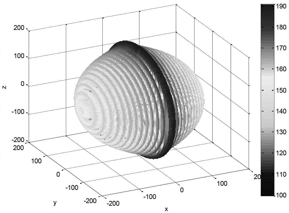
[0020] Step 1: Test the near-field pattern of the antenna under test in the microwave anechoic chamber, and the test distance R=2m, so as to obtain the near-field data of the antenna under test Where θ is the test pitch angle, is the azimuth angle of the test; the step angle is 1°;

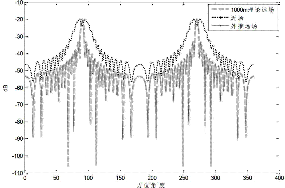
[0021] Step 2: Calculate the antenna far-field data

[0022]

[0023] in: is the antenna far-field data, is the Hankel function in spherical coordinates, Is the associated legendre function of nth order m, θ 0 is the pitch angle of the far field, is the azimuth of the far field, R is the near field distance, k is the wave number, e is the exponent power, j is an imaginary number, and D is the maxi...


PUM


Abstract

The invention relates to an antenna directional pattern testing method based on spherical surface near-field scanning extrapolation. Through near field testing, a far-field directional pattern can be obtained by subjecting obtained data to arithmetic extrapolation, so the testing distance is reduced and plane wave conditions required by cylindrical wave test are not required. A three-dimensional direction pattern obtained finally can analyze performance of an antenna more clearly and visually, and has great engineering practical value. The testing method can realize effective close-range antenna testing, saves testing cost, lowers testing difficulty, and meanwhile aims to obtain the three-dimensional direction pattern of a tested antenna so as to analyze performance of the antenna more accurately.

Description

technical field [0001] The invention belongs to the field of microwave measurement, in particular to an antenna pattern testing method based on spherical near-field scanning extrapolation. Background technique [0002] In the antenna test, it is always hoped that the radiation pattern of the antenna in the far field can be obtained, and the distribution of the antenna radiated energy in space can be represented by a graphic method. Generally, when the test frequency is high and the physical size of the antenna is large, it is difficult for the ordinary indoor test site to meet the test conditions, and an outfield test is required. However, in addition to the high cost of the outfield test, due to its long distance and environmental Openness makes the test extremely vulnerable to external interference, and it is not conducive to confidentiality. However, the current engineering test only analyzes the performance of the antenna by drawing the E-plane and H-plane of the antenn...

Claims


Application Information

Patent Timeline
Patent Type & Authority Applications(China)
IPC IPC(8): G01R29/10
Inventor 李南京王剑飞冯引良李瑛刘宁杨博陈卫军刘琦郭淑霞
Owner NORTHWESTERN POLYTECHNICAL UNIV
Why Eureka
Try Eureka