Portable optical axis detecting system of laser range finder

A technology of laser ranging machine and detection system, which is used in radio wave measurement systems, optics, measurement devices, etc.

CN103245940AActive Publication Date: 2013-08-14SOUTH WEST INST OF TECHN PHYSICS
3 Cites 7 Cited by

Patent Information

Authority / Receiving Office
CN · China
Patent Type
Applications(China)
Current Assignee / Owner
Publication Date
2013-08-14

Smart Images

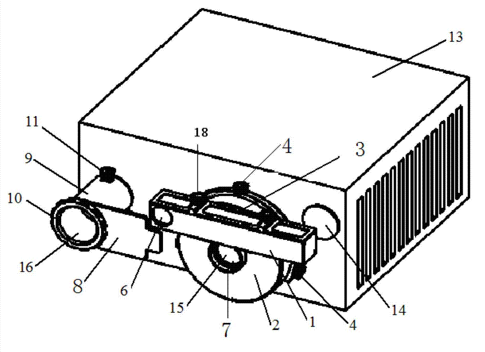
  • Figure 1
    Figure 1
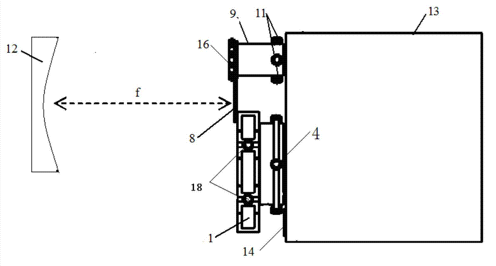
  • Figure 2
    Figure 2
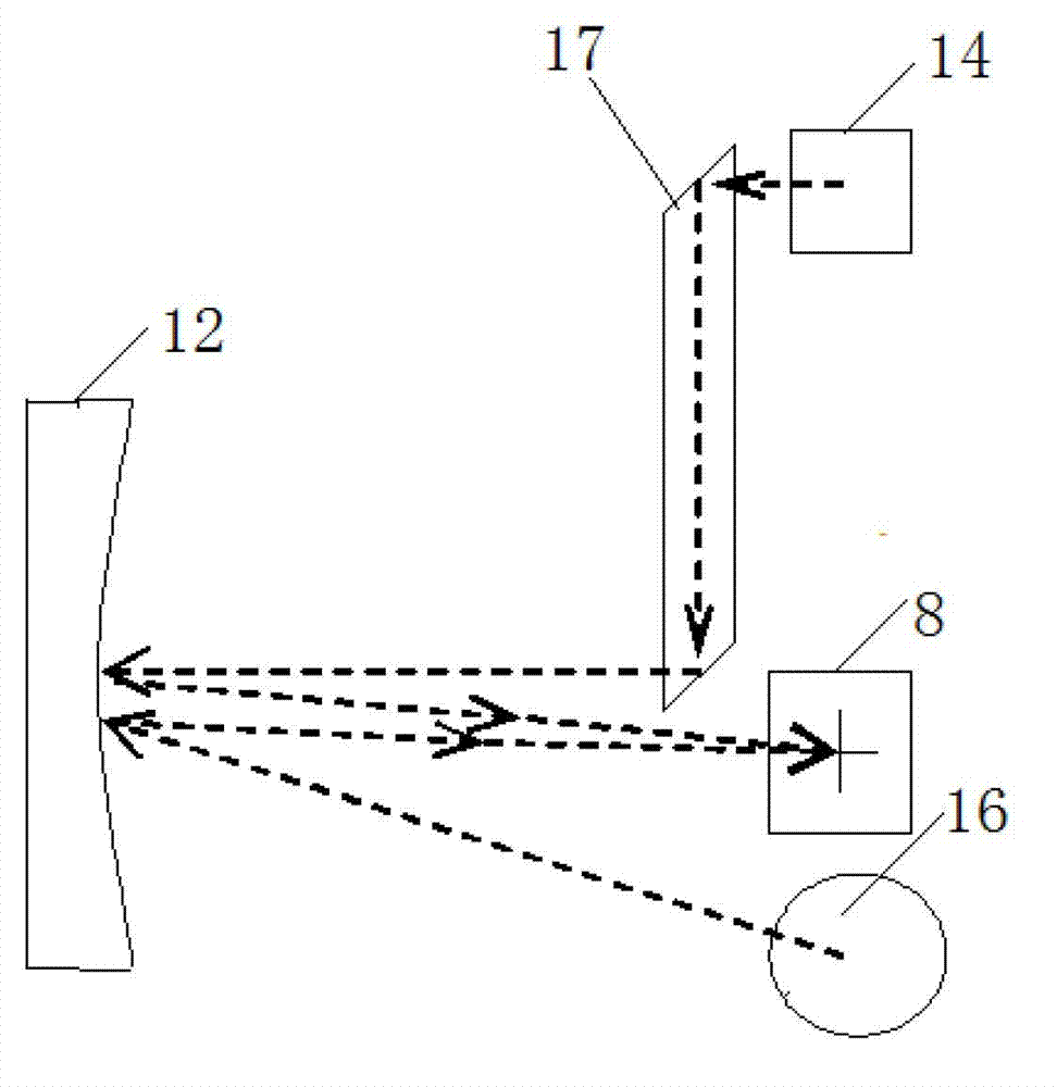
  • Figure 3
    Figure 3
Patent Text Reader

Abstract

The invention provides a portable optical axis detecting system of a laser range finder, which comprises a slanting square prism component (3), a target plate component (9) and a small-diameter reflector (12), wherein the target plate component comprises a target plate (8) fixedly connected to the shaft end of a support cylinder body through a target plate clamping ring (10); the slanting square prism component (3) comprises a slanting square prism bracket (2) with a receiving light through hole (7) formed in the center, and a slanting square prism table (1) fixedly connected above the receiving light through hole; a front light through hole (6) and a rear light through hole (5) are fabricated in diagonal lines at two ends of a rectangular frame groove of the slanting square prism table respectively; and a slanting square prism (17) is arranged in the rectangular frame groove of the slanting square prism table. When passing through a first 45-degree reflecting surface of the slanting square prism, an aiming optical path of the laser range finder generates 90-degree refraction, is refracted to another 45-degree reflecting surface, and generates 90-degree refraction again, and the optical path after the refraction is parallel to that before the refraction.
Need to check novelty before this filing date? Find Prior Art

Description

technical field

[0001] The invention belongs to a device for debugging, checking and correcting the optical axis of a laser distance measuring machine in the field environment. Background technique

[0002] As a distance sensor, the laser range finder generally includes three systems: the transmitting system, the receiving system and the aiming system. Whether the parallelism of the optical axes of these three systems meets the requirements is one of the keys to whether the technical indicators of the entire range finder can be achieved. one. Generally, the distance between the optical axes of the repetition-frequency air-to-air laser range finder is relatively large. Taking the XX model laser range finder as an example, the maximum distance between the optical axes of the aiming system and the transmitting system is as follows: Figure 4 Shown in d (d is 268mm). To meet the requirements of three optical axis adjustments, the optical aperture of the reflector should include...

Examples

Embodiment Construction

[0017] refer to Figure 1 to Figure 5 . In a preferred embodiment described below, the optical axis detection system of the portable laser rangefinder is composed of three parts: a rhomboid prism assembly, a target plate assembly, and a small-diameter reflector. Such as figure 1 shown. The orthorhombic prism assembly and the target plate assembly of the device are respectively pressed figure 2 The installation position shown is installed on a laser rangefinder that requires optical axis adjustment. The rhomboid prism assembly 3 is fixedly connected to the side of the rectangular box of the laser rangefinder 13, and the center is formed with a rhomboid prism bracket 2 with a receiving light hole 7 and a rhomboid prism seat 1 fixedly connected above the aperture of the receiving light hole 7 Composition, the receiving aperture 7 coaxially passes through the receiving antenna window 15, and is located at the front end of the aiming antenna window 14, and the rhombic prism a...