Multiple-exposure image fusion method and device

An image fusion and multi-exposure technology, applied in the field of image processing, to achieve the effect of improving image quality and processing speed

Active Publication Date: 2013-08-14
RICOH KK
View PDF9 Cites 46 Cited by
  • Summary
  • Abstract
  • Description
  • Claims
  • Application Information

AI Technical Summary

Problems solved by technology

This technique requires the known exposure time of the image to calculate the camera response function, and then generate an HDR image, but it also needs to be tone-mapped to display the above results

Method used


Image

  • Multiple-exposure image fusion method and device
  • Multiple-exposure image fusion method and device
  • Multiple-exposure image fusion method and device

Examples


no. 1 example

[0065]

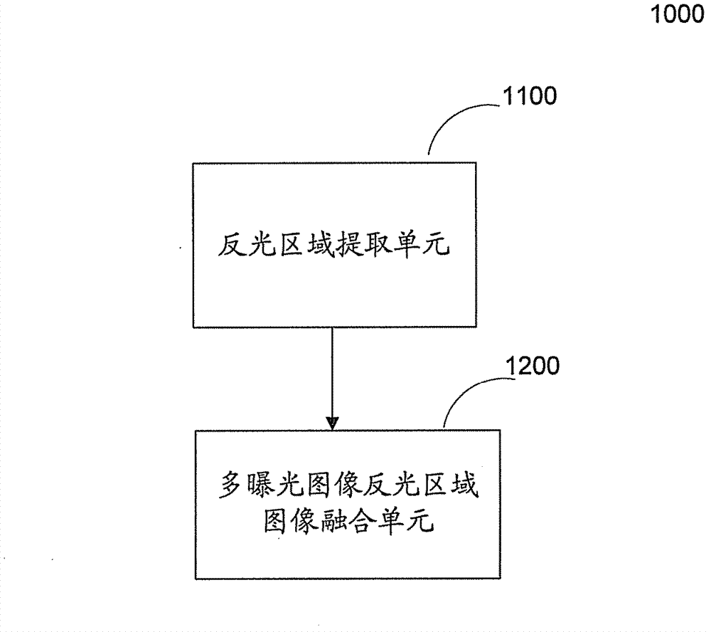
[0066] figure 1 It is an overall block diagram of a multi-exposure image fusion apparatus 1000 according to an embodiment of the present invention.

[0067] like figure 1 As shown, the multi-exposure image fusion apparatus 1000 may include: a reflective area extraction unit 1100 and a multi-exposure image reflective area fusion unit 1200 .

[0068] The reflective area extraction unit 1100 is used to extract the reflective area of ​​each image of multiple images of the same scene with different exposure levels

[0069] Preferably, the plurality of images with different exposure levels include overexposed and underexposed images.

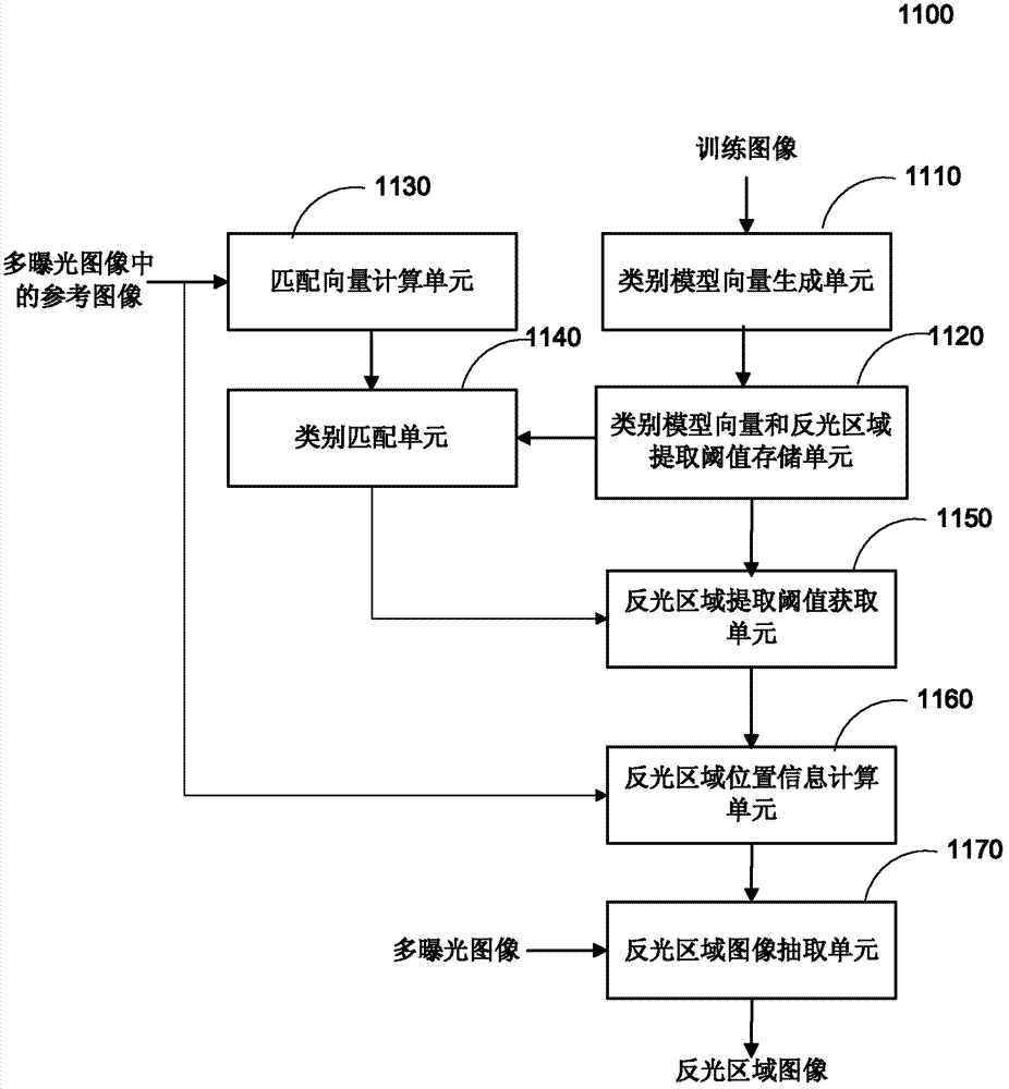
[0070] As an example, the reflective area extraction unit 1100 may use a predetermined image classifier to classify the plurality of images with different exposure degrees into each predetermined category, and then use the reflective area extraction threshold associated with each predetermined category to extract the plurality of exposure...

no. 2 example

[0196]

[0197] Figure 11 The overall configuration of the multi-exposure image fusion apparatus 2000 according to the second embodiment of the present invention is illustrated.

[0198] Figure 11 The second embodiment shown with figure 1 The first embodiment shown differs in that a quality enhancement unit 2300 is added. because Figure 11 The reflective area extraction unit 1100 and the multi-exposure image reflective area image fusion unit 1200 in the figure 1 are the same, and will not be repeated here. The operation of the quality enhancement unit 2300 is mainly described below.

[0199] The quality enhancement unit 2300 may perform decolorization processing on the reconstructed reflective area image.

[0200] In the original image as well as the reconstructed image, there may be color contamination caused by the light source. In the RGB color space, when the pixel values ​​of the R, G, and B color channels of the color image are equal, the color image is rende...

no. 3 example

[0219]

[0220] Figure 13 The overall configuration of a multi-exposure image fusion apparatus 3000 according to a third embodiment of the present invention is illustrated.

[0221] Figure 13 The third embodiment shown with Figure 11 The second embodiment shown is different in that there is an extra sticking-back unit 3400 . because Figure 13 The reflective area extraction unit 1100, the multi-exposure image reflective area image fusion unit 1200, the quality enhancement unit 2300 and the Figure 11 are the same, and will not be repeated here. The operation of the paste back unit 3400 will be described below with emphasis.

[0222] The sticking unit 3400 sticks the image enhanced by the quality enhancing unit 2300 back to, for example, the corresponding position of the aforementioned reference image, to obtain the final composite result image. For example, a method based on solving the Poisson equation in the article Poisson Image Editing by Patrick Perez et al. ca...


PUM


Abstract

The invention discloses a multiple-exposure image fusion device and method. The multiple-exposure image fusion device comprises a reflective area extraction unit and a multiple-exposure image reflective area fusion unit, wherein the reflective area extraction unit is used for extracting a reflective area of each image in a plurality of images with different exposure degree in a same scene; and the multiple-exposure image reflective area fusion unit is used for the fusion of the image with a plurality of reflective areas. The multiple-exposure image fusion device and the multiple-exposure image fusion method only perform the fusion operation on a reflective area rather than a plurality of whole images, so that processing speed is significantly increased; and the device and the method are used for the situation of a high real-time demand.

Description

technical field [0001] The present invention generally relates to the field of image processing, and more particularly to a method and apparatus for fusion of multi-exposure images. Background technique [0002] Images captured in certain situations often have highlighted or reflective areas, such as those captured in a camera or projector-camera system, causing content within the highlighted areas of the captured image to be invisible or indiscernible. [0003] For example, the whiteboard image contains strong specular reflection, which increases the dynamic range of the image, while the dynamic range of ordinary digital photography and display equipment is much smaller than the above-mentioned value. stroke information) will not be captured. [0004] At present, from the point of view of software development, there are mainly two methods to solve the limitation of the dynamic range of digital cameras. One is the High Dynamic Range (HDR) image generation technique. This ...

Claims


Application Information

Patent Timeline
Patent Type & Authority Applications(China)
IPC IPC(8): G06T5/50
Inventor 赵颖宫卫涛
Owner RICOH KK
Why Eureka
Try Eureka