Supercharge Your Innovation With Domain-Expert AI Agents!

Electrocar motor winding wire end twisting machine

A technology of motor winding and kinking machine, applied in the field of electric vehicle motor winding wire kinking machine and kinking machine, can solve the problems of kinking and other problems that are not suitable for electric vehicle motor winding wire ends, and achieves reduction of vibration and noise, good versatility, and high processing efficiency. Effect

Active Publication Date: 2015-04-22
WENLING JIUZHOU ELECTROMECHANICAL
View PDF4 Cites 0 Cited by
  • Summary
  • Abstract
  • Description
  • Claims
  • Application Information

AI Technical Summary

Problems solved by technology

[0004] The above-mentioned automatic head-twisting machine for the armature coil winding of a DC motor realizes the automatic head-twisting processing of the armature wire of the DC motor around the wire head. Kinks in winding wire ends

Method used


Image

  • Electrocar motor winding wire end twisting machine
  • Electrocar motor winding wire end twisting machine
  • Electrocar motor winding wire end twisting machine

Examples


Embodiment 1

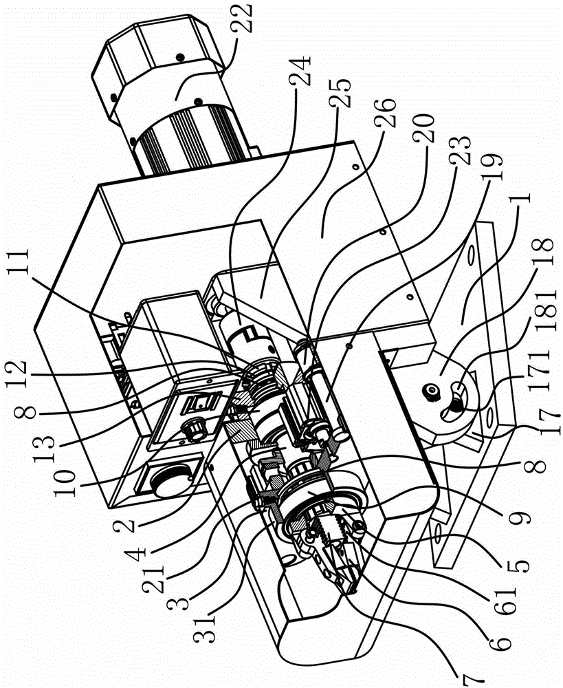
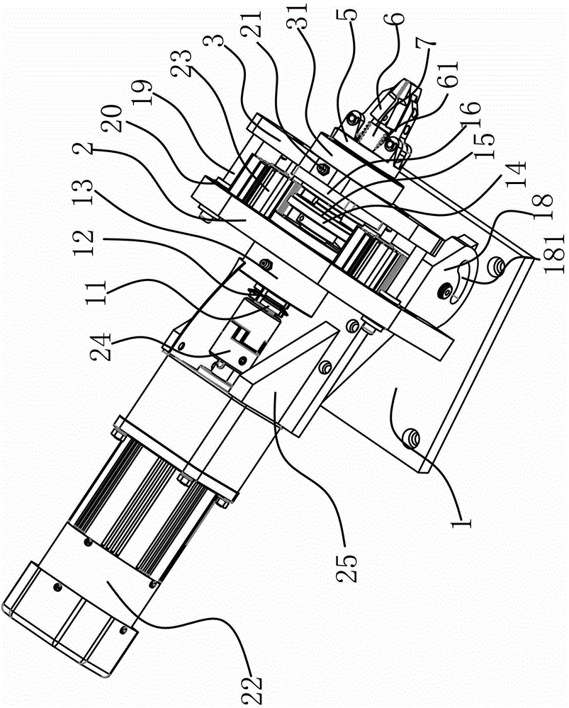
[0030] The electric vehicle motor winding wire head twisting machine includes a frame 1, a support plate 2, a push plate 3, a rotating main shaft 4, a clamp seat 5, a twisting clamp 6, a fixed bracket 25, a fixed seat 31, a drive motor 22, a drive cylinder 23, and a guide Mechanism, lubrication positioning structure, brake mechanism and angle adjustment mechanism.

[0031] Specifically, as figure 1 As shown, the support plate 2 is arranged on the frame 1, and the support plate 2 is also provided with a dust cover 26 for preventing external dust from entering the inside of the kink machine. The angle adjustment mechanism is arranged between the support plate 2 and the frame 1, and is used to change the angle formed by the support plate 2 and the frame 1, thereby adjusting the direction of the entire twisting machine. In this embodiment, the angle adjustment mechanism includes a hinge block one 17 fixed on the frame 1 and a hinge block two 18 fixed on the support plate 2, the h...

Embodiment 2

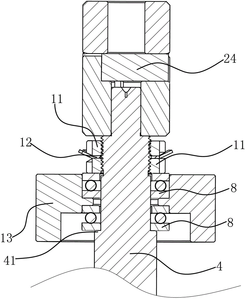
[0037] The technical solution in this embodiment is basically the same as the technical solution in Embodiment 1, the difference is that in this embodiment, the lubricating positioning structure includes a thrust ball bearing 8 and a round nut 11, and the rotating main shaft 4 has a shoulder 41, One end of the thrust ball shaft bears against the shaft shoulder 41 , and the other end is positioned by two round nuts 11 screwed on the rotating main shaft 4 , and a stop washer 12 is arranged between the round nuts 11 . The above installation method has a simple structure and is easy to implement.

Embodiment 3

[0039] The technical solution in this embodiment is basically the same as the technical solution in embodiment one or embodiment two, the difference is that in this embodiment, the brake mechanism includes a brake disc 14 fixed on the rotating main shaft 4, a push plate 3 A brake block 16 is provided at the position facing the brake disc 14, and the brake block 16 has a brake pad 15 corresponding to the position and shape of the brake disc 14, and when the push plate 3 is close to the support plate 2 The brake pads 15 are in contact with the brake disc 14 . Push plate 3 moves backward and in the process that kink pliers 6 are opened, brake block 16 is close to brake disc 14, and the brake disc 15 on the brake block 16 and brake disc 14 rub against each other to make rotating main shaft 4 decelerate.


PUM


Abstract

The invention provides an electrocar motor winding wire end twisting machine and belongs to the technical field of machines. The problem that the current winding wire end twisting machine is not suitable for twisting an electrocar motor winding wire end is solved. The electrocar motor winding wire end twisting machine comprises a machine frame, a rotating main shaft and a driving motor, wherein a supporting plate is arranged on the machine frame; the driving motor is fixedly arranged on the supporting plate through a fixed bracket; a driving cylinder used for driving a pushing plate to be close to or go away from the supporting plate is also arranged on the supporting plate; a fixed base is arranged on the pushing plate; a clamp base is axially positioned on the fixed base; two twisting clamps are hinged to the external end of the clamp base; a rack is fixedly arranged at one end of the rotating main shaft close to the twisting clamps; circular arc teeth matched with the rack are arranged on the twisting clamps; a braking mechanism is arranged between the rotating main shaft and the pushing plate; and an angle adjusting mechanism is arranged between the supporting plate and the machine frame. An electrocar motor winding wire end is automatically twisted by the electrocar motor winding wire end twisting machine, the processing efficiency is high, and the production cost is reduced.

Description

technical field [0001] The invention belongs to the technical field of machinery, and relates to a twisting machine, in particular to a twisting machine for winding wire ends of electric vehicle motors. Background technique [0002] Electric vehicle motors are used to drive electric vehicles. At present, electric vehicle motors generally use three-phase permanent magnet DC brushless motors. This type of motor must have the characteristics of high efficiency, wide speed range, low speed, high torque, and strong overload capacity. These performance characteristics and requirements determine that the winding design of this type of motor must be wound with wires with a large cross-sectional area. In actual production, multiple enameled wires are plied into a bundle for winding. Together, so that multiple enameled wires can be turned on at the same time. Since this motor is generally designed as three-phase or more phases, there are six or more wire heads that need to be twiste...

Claims


Application Information

Patent Timeline
Patent Type & Authority Patents(China)
IPC IPC(8): H02K15/04
CPCY02T10/641Y02T10/64
Inventor 张学斌蒲道勇钟治平
Owner WENLING JIUZHOU ELECTROMECHANICAL
Features
  • R&D
  • Intellectual Property
  • Life Sciences
  • Materials
  • Tech Scout
  • Unparalleled Data Quality
  • Higher Quality Content
  • 60% Fewer Hallucinations
Learn More