
Strengthened glass substrate cutting method

A tempered glass and substrate technology, which is applied to glass manufacturing equipment, glass cutting devices, welding/welding/cutting items, etc., can solve the problems of small cracks and particles in tempered glass substrates, difficulty in crack extension, and difficulty in controlling the direction of crack extension, etc. To achieve the effect of reducing costs, reducing operation time, and reducing the number of

Active Publication Date: 2013-08-14
罗泽系统株式会社
View PDF3 Cites 5 Cited by
  • Summary
  • Abstract
  • Description
  • Claims
  • Application Information

AI Technical Summary

Problems solved by technology

According to the mechanical cutting method, there is a problem that extremely small cracks and particles are generated on the surface of the tempered glass substrate
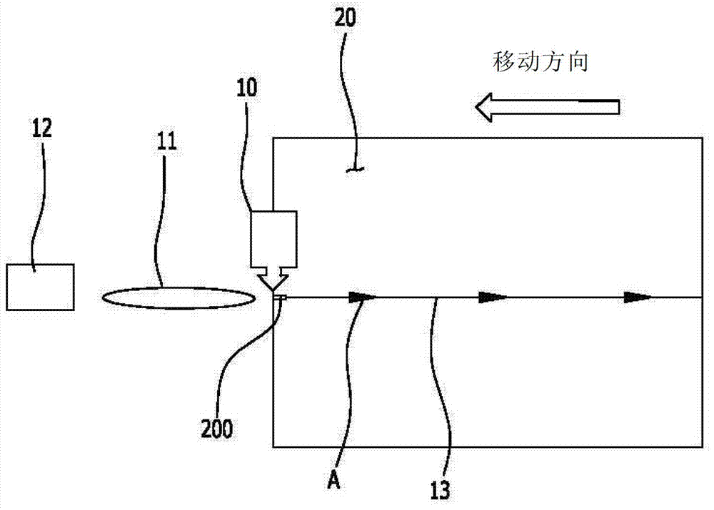
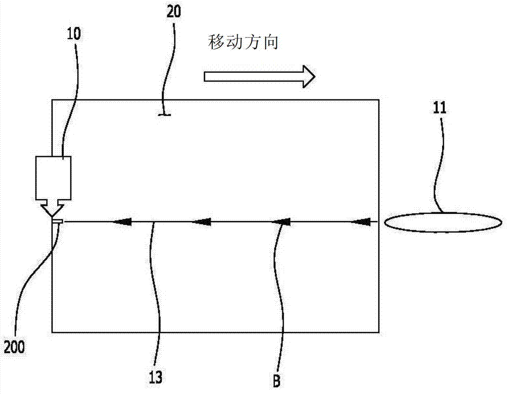
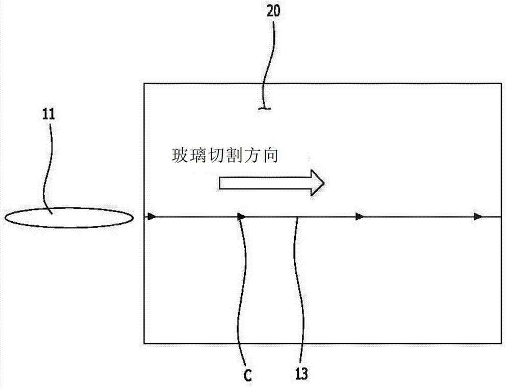
[0008] According to the conventional method of cutting a tempered glass substrate, while the scribe line 13 is sequentially formed from the initial crack 200 of the tempered glass substrate 20 to the cutting end point of the tempered glass substrate 20, the crack is extended by cooling the scribe line 13, however, for the tempered glass As far as the substrate is concerned, it is difficult to extend the crack to the desired length and control the direction of the crack extension in this method.

Method used


Image

  • Strengthened glass substrate cutting method
  • Strengthened glass substrate cutting method
  • Strengthened glass substrate cutting method

Examples


Embodiment Construction

[0025] The present invention will be described more fully hereinafter with reference to the accompanying drawings, which show exemplary embodiments of the invention. However, the present invention can be carried out in many different ways and should not be construed as limited to the embodiments herein, but changes and modifications can be made to these exemplary embodiments which still fall within the scope of the present invention as defined by the appended claims. within the spirit and scope of the invention. It should be understood that although the terms first, second, etc. may be used in the present invention to describe various constituent elements, these constituent elements should not be limited by these terms. These terms are only used to distinguish a constituent element from other constituent elements. For example, a first element described below could be termed a second element, and thus, a second element could also be termed a first element, without departing fr...


PUM


Abstract

Disclosed is a strengthened glass substrate cutting method wherein a strengthened glass substrate can be cut using only a laser scribing process, without any use whatsoever of a mechanical breaking process or cooling process. The strengthened glass substrate cutting method comprises the steps of: forming an initial crack in the place where the cutting of the strengthened glass substrate will start; pre-forming a heating line in the strengthened glass substrate by shining a laser beam, via an optical heating instrument, progressively towards the initial crack from a place on the strengthened glass substrate where the initial crack was not formed; and, once the laser beam has been shone as far as the initial crack, using the laser beam to cut the strengthened glass substrate along the previously formed heating line, using the initial crack as the starting point.

Description

technical field [0001] The present invention relates to a method of cutting tempered glass, and more particularly to a method of cutting tempered glass by using a laser beam. Background technique [0002] Generally, the tempered glass substrate is cut using a mechanical cutting method, a chemical cutting method, and a laser cutting method. A mechanical cutting method uses a diamond wheel or a sandblasting machine; a chemical cutting method uses a wet etching method. According to the mechanical cutting method, there is a problem that extremely small cracks and particles are generated on the surface of the tempered glass substrate. According to the chemical cutting method, there are problems of environmental pollution caused by chemicals and low productivity caused by relatively long-time operation. In addition, according to the conventional laser cutting method, after the initial crack is formed, the crack is extended by irradiating a laser beam, and then a mechanical cutti...

Claims


Application Information

Patent Timeline
Patent Type & Authority Applications(China)
IPC IPC(8): C03B33/02C03B33/09B23K26/38
CPCB23K26/38B23K26/4075C03B33/091B23K26/40B23K2103/50Y10T225/12C03B33/02C03B33/033C03B33/09
Inventor 赵镛钦朴赫文盛郁柳基龙
Owner 罗泽系统株式会社
Learn More