Device for monitoring a pump

A technology of centrifugal pumps and components, applied in pump control, non-variable pumps, ultrasonic/sonic/infrasonic transmission systems, etc., to prevent deterioration and reduce errors

Active Publication Date: 2013-08-14
KSB AG
View PDF11 Cites 7 Cited by
  • Summary
  • Abstract
  • Description
  • Claims
  • Application Information

AI Technical Summary

Problems solved by technology

However, this monitoring method is only suitable for centrifugal pumps that deliver optically transparent media

Method used


Image

  • Device for monitoring a pump

Examples


Embodiment Construction

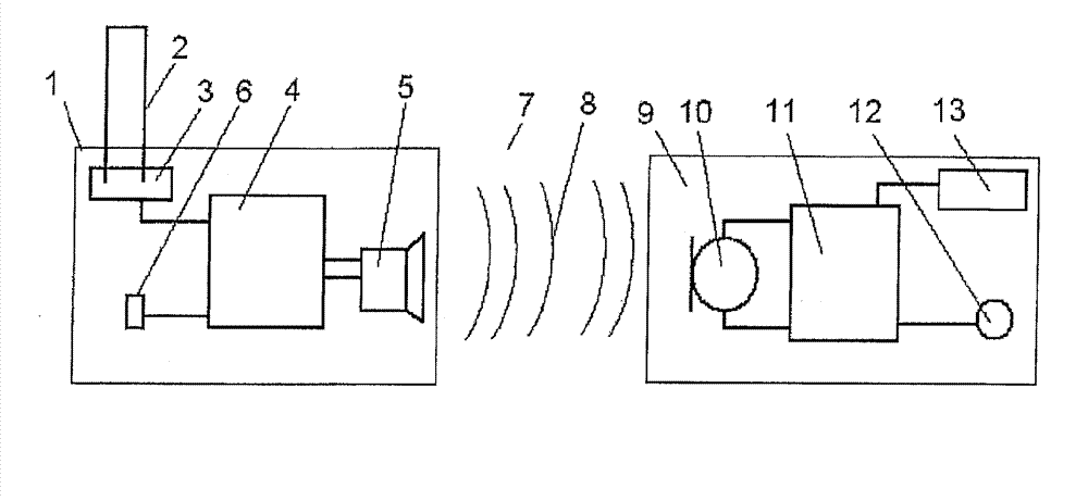
[0022] figure 1 A device for monitoring a centrifugal pump or a rotating component in a system comprising a centrifugal pump is shown, which device consists of a first unit 1 which is fixedly connected to the component to be monitored. In addition to the arrangement directly adjacent to the component, there is also the possibility of integrating the first unit directly into the component. This is provided, for example, if the component consists of a casting material which can be cast at relatively low temperatures, for example a polymer material, in particular polymer concrete or a mineral casting. For this purpose, the configured, self-contained and cordless first unit is cast, for example, into the impeller of a centrifugal pump. This component itself is not shown for simplicity of illustration.

[0023] The first unit 1 comprises a sensor 2 for detecting component properties, which is connected to the first unit 1 at a sensor connection 3 . It is also possible that sever...


PUM


Abstract

A device and a method for monitoring rotating components in centrifugal pumps or systems which comprise centrifugal pumps is provided. The device includes a first unit which is located on or in the component to be monitored having at least one component property sensor, a sensor signal evaluation unit, a transmitting unit for transmitting analysis results to a receiver arranged spatially separate from the monitored component, and a source for supplying power. The device further includes a second unit having a receiver unit, a transmitted signal evaluation unit, and a sensed component property display and / or information communication element. The analysis result transmission from the first unit to the second unit is acoustic.

Description

technical field [0001] The invention relates to a device and a method for monitoring a centrifugal pump or a rotating component in a plant comprising a centrifugal pump. Background technique [0002] Centrifugal pumps are used in a large number of installations where they are sometimes subjected to very harsh conditions. Therefore, depending on the application, the state of the centrifugal pump, especially the impeller, must be precisely monitored in order to avoid damage to the centrifugal pump or the entire plant. [0003] DE 40 055 03 A1 shows a device for monitoring an impeller by means of a light emitter (Lichtsender) and an optical probe. This form of monitoring requires fixed centering of light emitters and sensors on the leading edge of the wing. However, this monitoring method is only suitable for centrifugal pumps which convey optically transparent media. [0004] A vacuum pump with a pump stator and a pump rotor is known from DE 10 2008 019 472 A1, the pump rot...

Claims


Application Information

Patent Timeline
Patent Type & Authority Applications(China)
IPC IPC(8): F04D15/00H04B11/00
CPCH04B11/00F04D15/0088
Inventor A.贝姆G.埃贝尔特S.劳厄U.克隆费尔德J.舒莱雷尔G.赫青格B.施拉姆
Owner KSB AG
Why Eureka
Try Eureka