Workpiece stamping intelligent control process and intelligent control manipulator

An intelligent control and manipulator technology, applied in the direction of program control manipulators, manipulators, manufacturing tools, etc., can solve the problems of hand crush, disability and insecurity, and achieve the effect of enhancing stability, convenient operation and obvious effect.

Inactive Publication Date: 2013-08-21
FOSHAN DINGFENG ROBOT
6 Cites 48 Cited by

AI-Extracted Technical Summary

Problems solved by technology

The current punching equipment is generally operated manually when stamping parts, that is, manually put the workpiece on the mold of the punching ...

Method used

(8) The first servo motor 002 is connected with a speed reducer 015 and a backlash buffer 018 to control the swing angle of the mechanical arm, and ensure accuracy and stability by the backlash buffer 018;
[0049] The swing arm mo...

Abstract

The invention discloses a workpiece stamping intelligent control process. The workpiece stamping intelligent control process controls automatically and satisfies all actions to be operated coherently to effectively improve working efficiency, no manual work is needed, safety is improved and cost is effectively saved. Product quality is guaranteed to enable products to meet market demands. The invention further provides an intelligent control manipulator implementing the process. Through an efficient, accurate, flexible, safe operation mode flexible in design, the intelligent control manipulator is convenient to operate, production efficiency is greatly improved, structural design is reasonable, design mode is flexible, effects are obvious, process persistence is high, raw materials are saved and energy consumption is quite low; a regulation and control type industrial control process satisfies different demands, the structural design enhances smoothness, swing precision is guaranteed, and machining process is guaranteed to be completed automatically, continuously and effectively; and conventional manual or semi-automatic machining modes are replaced, and resources are saved.

Application Domain

Programme-controlled manipulatorMetal-working feeding devices +2

Technology Topic

Automatic controlMachining process +13

Image

  • Workpiece stamping intelligent control process and intelligent control manipulator
  • Workpiece stamping intelligent control process and intelligent control manipulator
  • Workpiece stamping intelligent control process and intelligent control manipulator

Examples

  • Experimental program(1)

Example Embodiment

[0033] Examples:
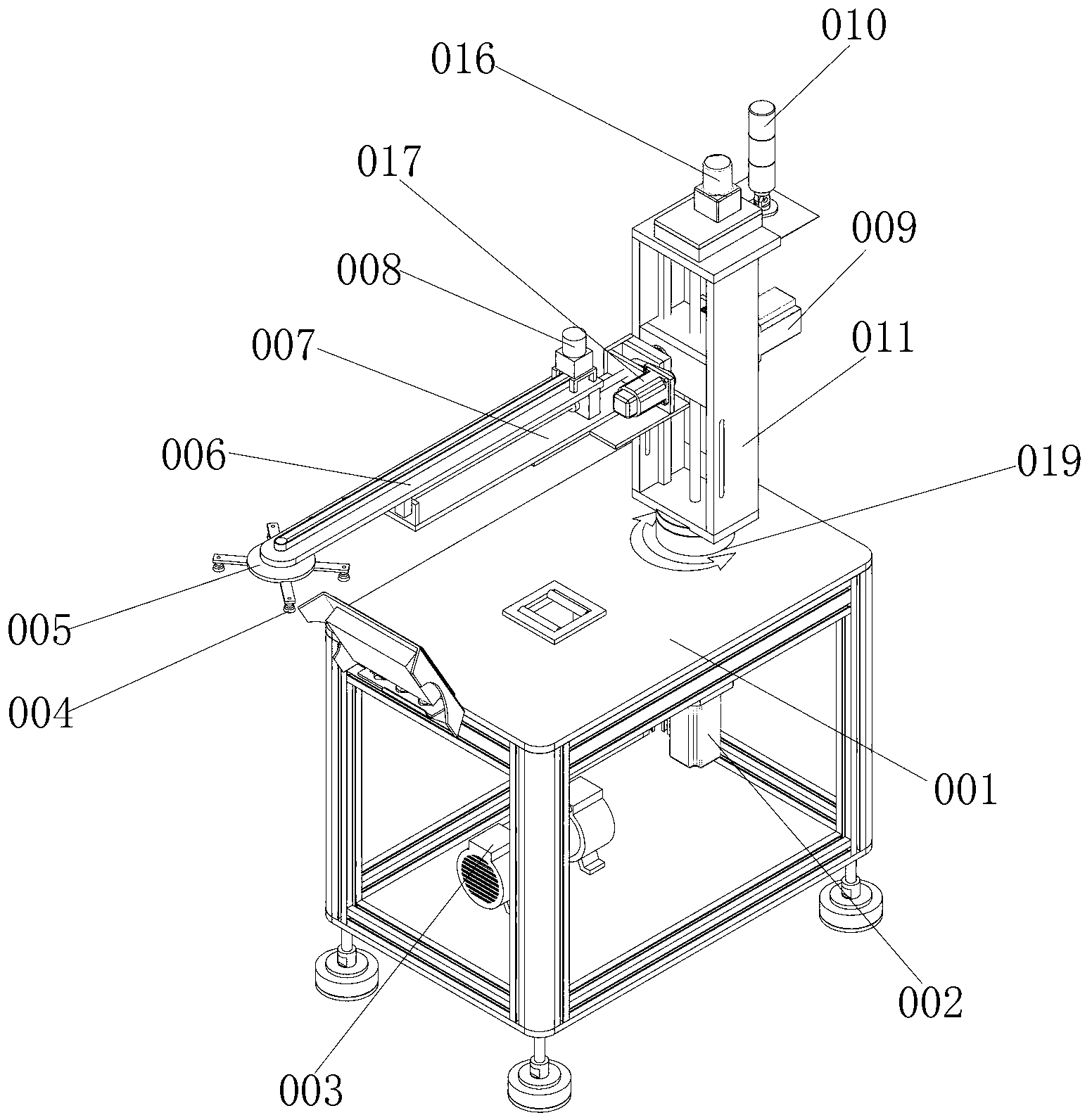
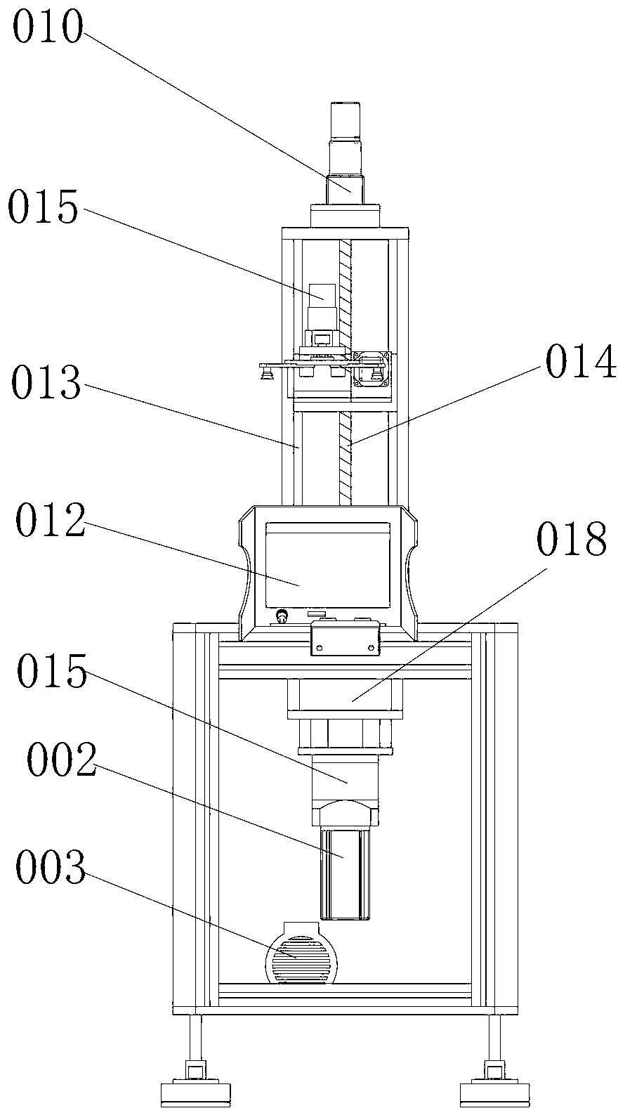
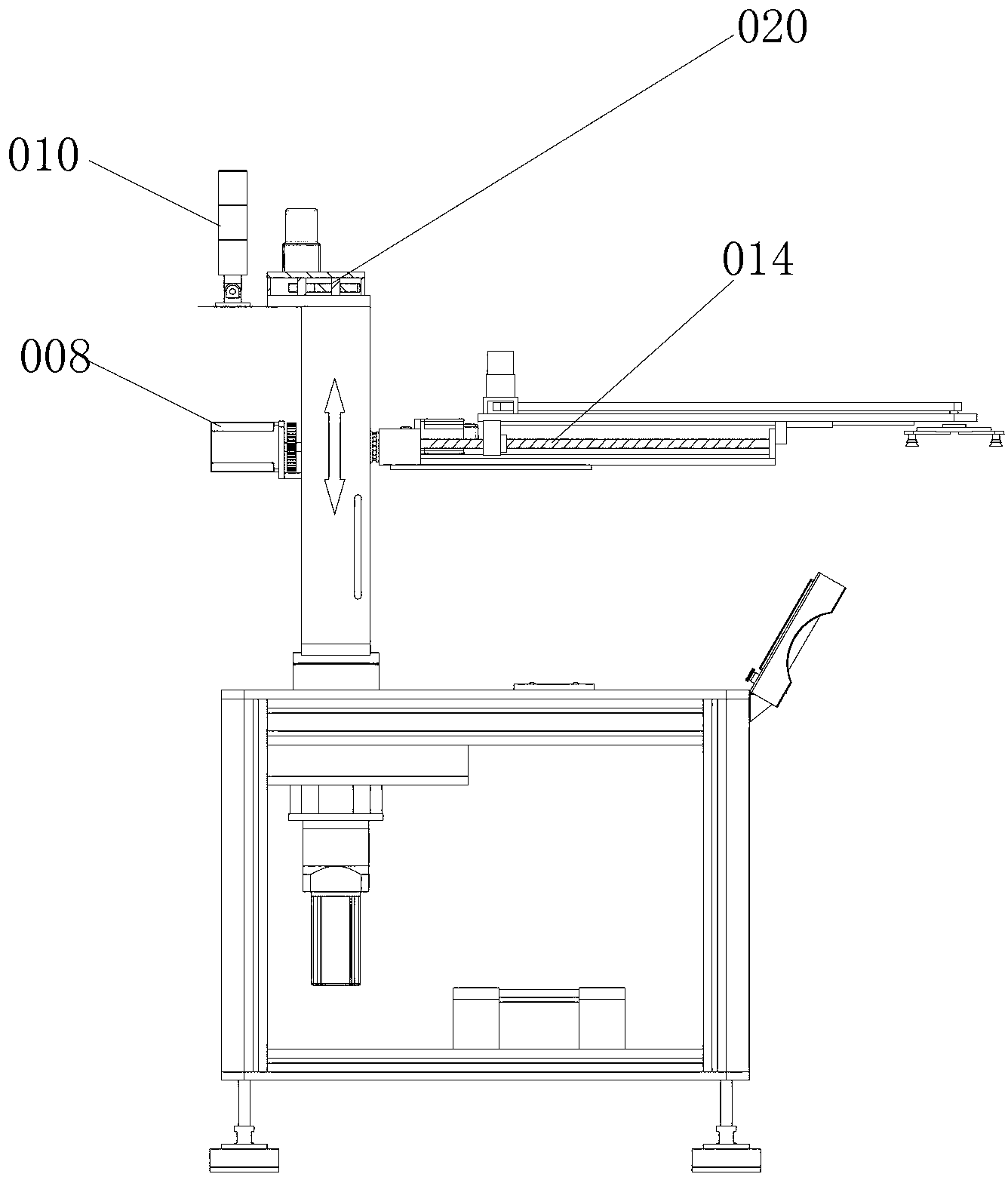
[0034] Such as figure 1 , 2 and image 3 As shown, the workpiece punching intelligent control process provided by this embodiment includes the following steps:
[0035] (1) Set up an intelligent control manipulator, which is composed of a control device 012, an actuator, and a driving device; the control device 012, the actuator, and the driving device are respectively set on the supporting machine, and the control device 012 is composed of a man-machine The interface control device 012 and the control system are composed of a thrust bearing 019 for increasing stability at the connection and fixing place between the support machine and the arm column 011.
[0036] (2) The actuator is composed of an arm column 011 and a mechanical arm arranged on the arm column 011 and a correction plate 005; the correction plate 005 is arranged at the front end of the mechanical arm, and the correction plate 005 is provided with Multiple sets of suction cups 004, the control machine 001 is equipped with a vacuum pump 003, the vacuum pump 003 is connected to the suction cup 004 and completes the vacuum conversion of the suction cup 004, the mechanical arm is extended by the rear arm and the front Arm composition.
[0037] (3) The driving device is composed of a first servo motor 002, a second servo motor 016, a third servo motor 017, a first stepping motor 008, a second stepping motor 009 and a transmission device; the first servo motor 002 is installed at the lower part of the supporting machine, the second servo motor 016 is installed at the top end of the upper part of the arm column 011, and the third servo motor 017 is installed on the upper end surface of the robot arm close to the arm column 011. A stepping motor 008 is arranged at the end connection of the side of the robot arm close to the arm column 011, and the second stepping motor 009 is arranged on the side of the third servo motor 017.
[0038] (4) The transmission device is provided with gears, and the first stepping motor 008 completes the turning function of the mechanical arm through gear transmission;
[0039] (5) A speed reducer 015 is arranged on the upper end of the second stepping motor 009, which drives the transmission belt to complete the movement of the correction disc 005 by increasing the torque;
[0040] (6) The transmission mechanism is provided with a ball screw 014, and the third servo motor 017 drives the ball screw 014 to link the front and back telescopic movement of the mechanical arm;
[0041] (7) The transmission mechanism is provided with a gear box 020 and a linear guide 013, a pair of gears are built-in, and the second servo motor 016 links the up and down movement of the mechanical arm along the linear guide 013 through the pair of gears;
[0042] (8) The first servo motor 002 is connected with a speed reducer 015 and a backlash buffer 018 to control the swing angle of the robot arm, and the backlash buffer 018 ensures accuracy and stability;
[0043] (9) In the above steps (4)-(7), the turning, telescoping, lifting, and movement of the correction plate 005 of the robotic arm are realized in linkage.
[0044] An intelligent control manipulator for realizing the above-mentioned processing technology, including a supporting machine platform, the control machine 001 is provided with an arm column 011, and the lower part of the control machine 001 includes a vacuum pump 003 and a mutually linked backlash buffer 018. Reducer 015 and first servo motor 002. One side of the arm column 011 includes an outwardly extending mechanical arm, which consists of a main arm 007 and a telescopic arm 006. The main arm 007 is close to the arm column 011 One side also includes a second stepping motor 009 and a third servo motor 017. The front end of the telescopic arm 006 includes a calibration disk 005. The lower end of the calibration disk 005 is connected to a plurality of suction cups 004. The upper end of the arm column 011 includes a second Servo motor 016 and gear seat. The main arm 007 also includes a first stepper motor 008, a ball screw 014 linked with it, and a timing belt.
[0045] The fixed connection between the arm column 011 and the control machine 001 further includes a thrust bearing 019. The upper end of the arm column 011 is provided with a signal indicator 010. The upper side of the plane platform of the control machine 001 includes a control device 012, which is composed of a human operation interface and an internal controller. The third servo motor 017 is provided with a motor base fixed on the main arm 007 to increase the torque.
[0046] The working principle of the present invention is as follows:
[0047] The horizontal movement mechanism slides back and forth at high speed, and the speed is 250-350mm per second to quickly pick up objects;
[0048] This part of the flip motion mechanism is designed to flip at an arbitrary set angle of 270 degrees. The key design is the 90-degree side stamping when the product is flipped, and the 180-degree stamping is the key design, and the desired angle can be flexibly set;
[0049] The swing arm movement mechanism is the transfer function of the stamping product from the origin to another point. The transfer time within the 270 degree angle range is 0.5-1 seconds, and the positioning is accurate and efficient.
[0050] When the rotary motion mechanism of the executive end sucks the stamped product, the product angle will change when the swing arm transfers the product from the origin to another position. The design here is 270 degrees, rotate the product angle, and set it to the desired position. This design greatly reduces the mold standard and high requirements of mold making, thereby enabling customers to reduce costs and increase efficiency.
[0051] The vertical movement mechanism is designed to lift and lower when sucking stamping products at a fixed station. The lifting speed is 50mm-60mm and the back and forth movement is no more than 1 second, and the total stroke is 300-500mm.

PUM

no PUM

Description & Claims & Application Information

We can also present the details of the Description, Claims and Application information to help users get a comprehensive understanding of the technical details of the patent, such as background art, summary of invention, brief description of drawings, description of embodiments, and other original content. On the other hand, users can also determine the specific scope of protection of the technology through the list of claims; as well as understand the changes in the life cycle of the technology with the presentation of the patent timeline. Login to view more.

Similar technology patents

Report data generating method and system

ActiveCN103473342ASimplify the docking processImprove work efficiency
Owner:BEIJING JOIN CHEER SOFTWARE

Cloud computing based password service system

InactiveCN104202421AImprove work efficiencyFast encryption and decryption
Owner:LANGCHAO ELECTRONIC INFORMATION IND CO LTD

Caking fertilizer crushing device for agriculture big data

Owner:安徽众力农业装备科技有限公司

Classification and recommendation of technical efficacy words

  • Improve work efficiency
  • improve security

Cooperation service platform facing different source data

InactiveCN101174957AImprove management level and qualityImprove work efficiency
Owner:NANJING UNIV OF FINANCE & ECONOMICS

Screw drilling tool, vertical drilling tool testing method and well inclination simulation testing equipment

InactiveCN111594144AReduced height requirementsImprove work efficiency
Owner:DEZHOU UNITED GASOLINEEUM MACHINERY

Method for intelligent automatic identification of transmission circuit parts

Owner:INFORMATION COMM COMPANY STATE GRID SHANDONG ELECTRIC POWER +2

Keyboard spill-proofing mechanism

ActiveUS7030330B2minimize manufacturing costimprove work efficiency
Owner:LITE ON SINGAPORE PTE LTD

Pesticide micro-capsule granules and preparation method thereof

InactiveCN102100229Alow toxicityimprove security
Owner:联合国南通农药剂型开发中心 +1

Method for achieving user authentication by utilizing camera

InactiveCN103678984Aimprove securityGuaranteed picture quality
Owner:湖北微模式科技发展有限公司
Why Eureka
Try Eureka