
Weighing clamping mechanism

A weighing and frame technology, applied in the direction of manipulators, program control manipulators, manufacturing tools, etc., can solve the problems of difficult cleaning and disinfection, complex structure of weighing and clamping mechanism, difficult adjustment, etc., to achieve sensitive operation, easy cleaning and Sterilization, the effect of improving movement precision

Active Publication Date: 2013-08-21
SHANGHAI TOFFLON SCI & TECH CO LTD
View PDF5 Cites 0 Cited by
  • Summary
  • Abstract
  • Description
  • Claims
  • Application Information

AI Technical Summary

Problems solved by technology

[0003] What the present invention aims to solve is the problem that the existing weighing and clamping mechanism has complex structure, difficult adjustment, difficult cleaning and disinfection

Method used


Image

  • Weighing clamping mechanism
  • Weighing clamping mechanism

Examples


Embodiment

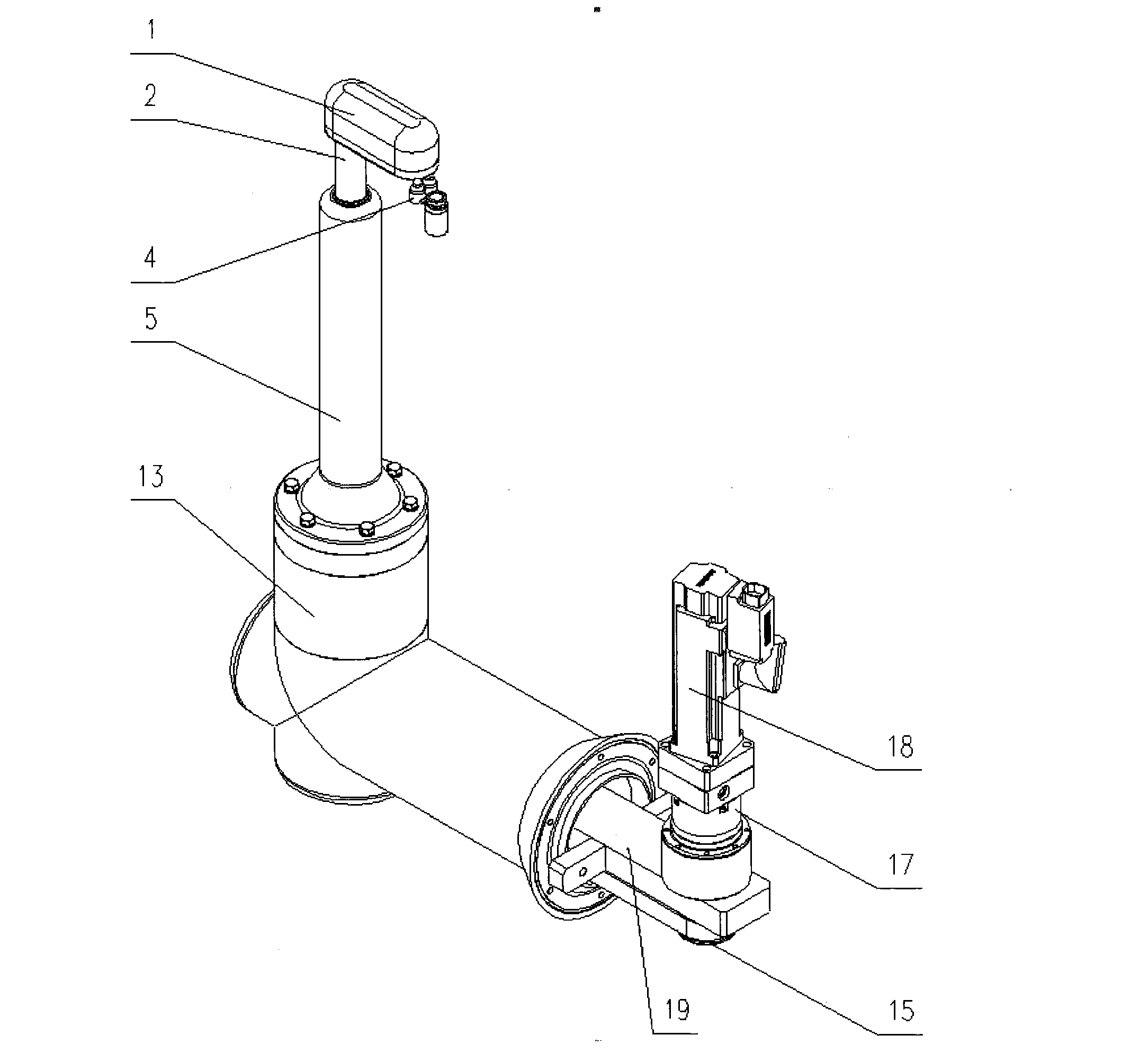
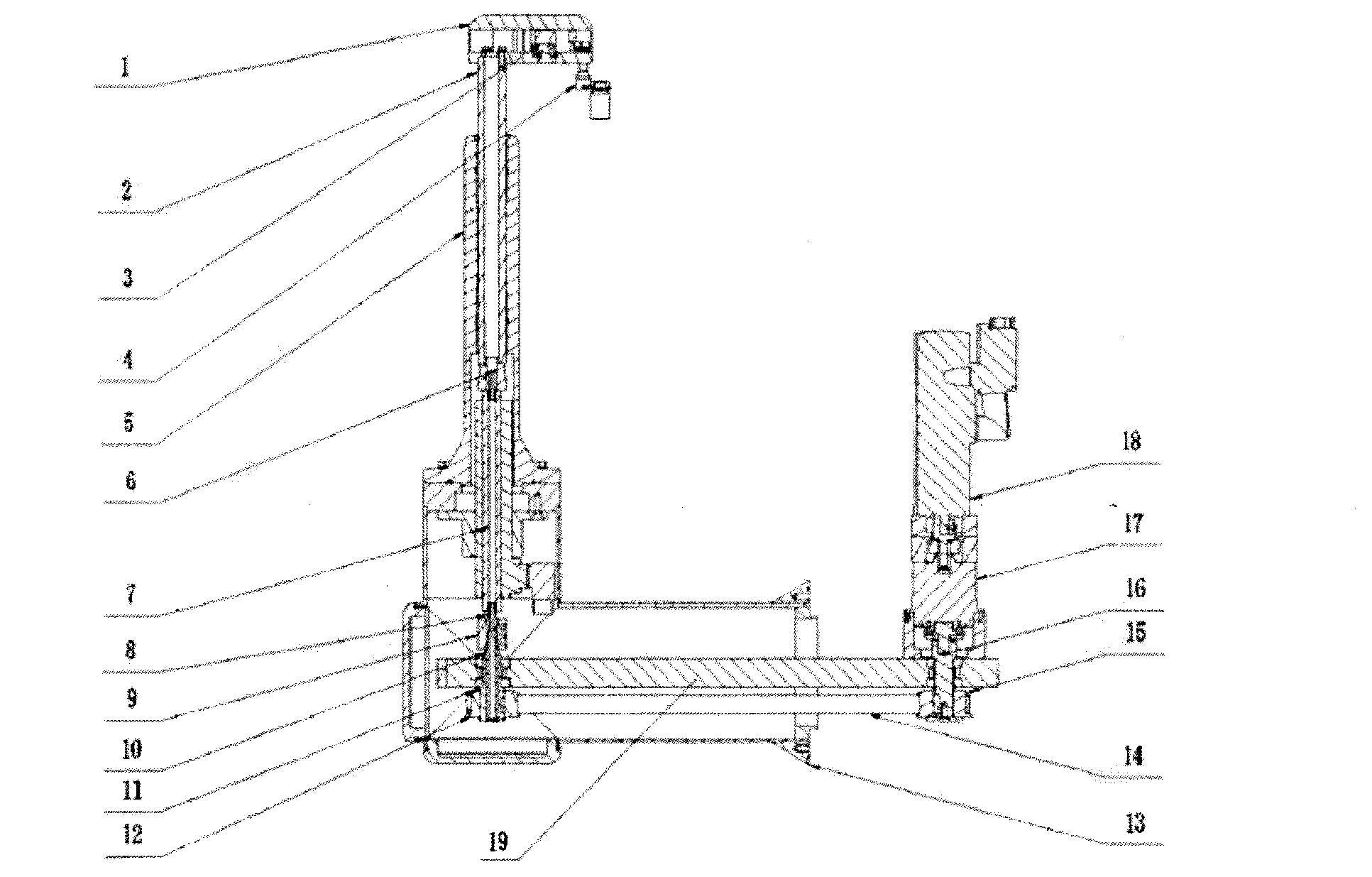
[0024] Such as Figure 1-2 As shown, it is a structural schematic diagram of the weighing and clamping mechanism provided by the present invention. A weighing and clamping mechanism includes a frame 13, and the frame 13 is in the shape of a hollow cross cylinder. Horizontally insert a positioning rod 19 in the frame 13, the left and right ends of positioning rod 19 are respectively provided with synchronous belt pulley one 12, synchronous belt pulley two 15, and synchronous belt pulley one 12, synchronous belt pulley two 15 overcoat one Timing belt 14. The right end of positioning rod 19 is exposed from the right side of frame 13 . Guide seat 5 is installed above the vertical direction cylinder on the left side of frame 13. A linear motor 7 is installed on the synchronous pulley 12, and the bottom end of the linear motor 7 is connected with the synchronous pulley 12 through a shaft assembly. One end is connected with the outer spline hollow shaft 10 through the coupling two...


PUM


Abstract

The invention discloses a weighing clamping mechanism which comprises a rack. The weighing clamping mechanism is characterized in that a positioning rod is arranged in the rack, the left end of the positioning rod and the right end of the positioning rod are provided with a first synchronous belt wheel and a second belt synchronous wheel respectively, the first synchronous belt wheel and the second belt synchronous wheel are connected through synchronous belts, and the right end of the positioning rod is exposed out of the right side of the rack. A guide holder is arranged at the upper portion of the left side of the rack, a linear motor is arranged on each synchronous belt wheel, the bottom end of the linear motor is connected with each synchronous belt wheel through a shaft assembly, the top end of the linear motor is connected with the bottom end of a guide rod through a coupler, the top end of the guide rod is exposed out of the guide holder, and a clamping assembly is arranged on the top end of the guide rod. A speed reducer is arranged on each second synchronous belt wheel, the speed reducer is connected with the synchronous belt wheel through transmission shafts, and a servo motor is arranged on the speed reducer. The servo motor passes through the speed reducer, and drives the clamping assembly to rotate through a synchronous belt transmission mechanism. The linear motor drives the clamping assembly to move in a lifting mode through the guide rod. An air cylinder drives a bottle clamp to achieve opening or closing of the bottle clamp, and three kinds of motion are combined in order to achieve the functions of clamping, transporting and releasing.

Description

technical field [0001] The invention relates to a weighing and gripping mechanism for a filling machine, which belongs to the technical field of packaging equipment for food, medicine and cosmetics. Background technique [0002] The weighing and clamping mechanism in the prior art has complex structure, low stability, insensitive operation, and relatively loud noise; and most of them are purely mechanical structures, which cannot well meet the diversification of packaging materials. It is time-consuming and labor-intensive to adjust the mechanism when the product is replaced, which is troublesome. "Rigidity" and "low intelligence" are the main characteristics of weighing and clamping mechanisms in the current market. In addition, due to the complex structure, it is difficult to clean and sterilize, and cannot meet the increasingly stringent sterility requirements of pharmaceutical regulations. Contents of the invention [0003] The present invention aims to solve the pro...

Claims


Application Information

Patent Timeline
Patent Type & Authority Applications(China)
IPC IPC(8): B25J9/10
Inventor 郑效东
Owner SHANGHAI TOFFLON SCI & TECH CO LTD
Learn More