Cooling unit for traction system

A cooling unit and traction system technology, applied to locomotives and other directions, can solve the problems of heavy total weight, uncompact structure, and large overall volume, and achieve the effect of small maintenance workload, compact structure, and small volume

Active Publication Date: 2016-03-30
CRRC DALIAN INST CO LTD
View PDF7 Cites 0 Cited by
  • Summary
  • Abstract
  • Description
  • Claims
  • Application Information

AI Technical Summary

Problems solved by technology

Due to the scattered arrangement of the two cooling units, each cooling unit requires independent components such as radiators, fan units, and load-bearing support frames. The structure is not compact, the total volume is large, and the total weight is heavy.

Method used


Image

  • Cooling unit for traction system
  • Cooling unit for traction system
  • Cooling unit for traction system

Examples


Embodiment Construction

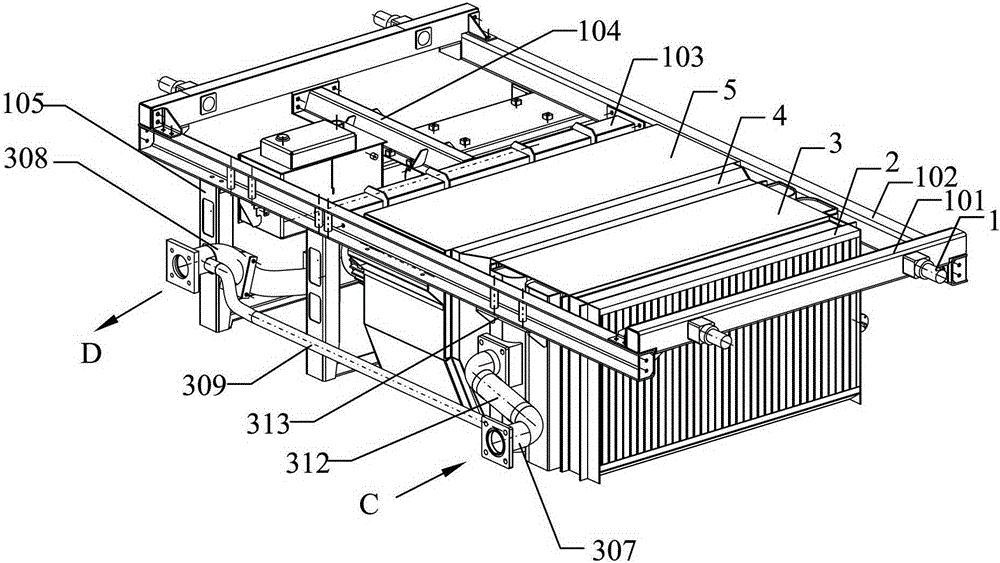
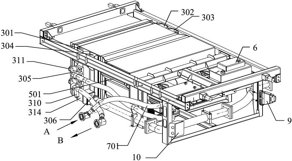
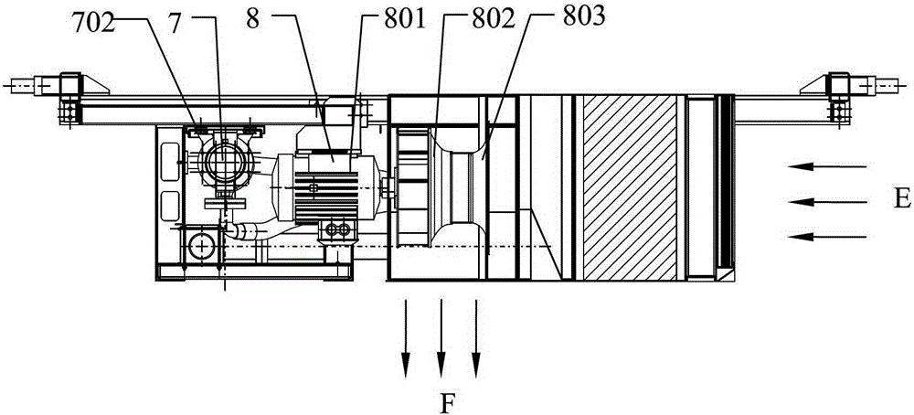
[0036] Such as Figure 1 to Figure 3 As shown, a cooling unit for a traction system includes a load-bearing support frame 1, an air filter device 2, a radiator 3, an air guide tube 4, a fan box 5, an expansion tank 6, a water pump 7, a fan unit 8 and fixed on the The electrical quick connector 9 and the junction box 10 on the carrying support frame 1 are described above.

[0037] The load-bearing support frame 1 includes 2 main load-bearing beams 101, 2 main load-bearing longitudinal beams 102, 1 auxiliary load-bearing beam 103, 1 auxiliary load-bearing longitudinal beam 104, and 4 columns 105 for ensuring the strength of the cooling unit. The main bearing beam 101 and the main bearing longitudinal beam 102 constitute a rectangular support frame for fixing the radiator 3 and the fan box body 5, and the auxiliary bearing beam 103 is fixed between the main bearing longitudinal beams 102 , the auxiliary load-bearing longitudinal beam 104 is fixed between the main load-bearing be...


PUM


Abstract

A cooling unit for a traction system comprises a bearing and supporting framework (1), an air filtering apparatus (2), a radiator (3), an air guide cylinder (4), a fan box body (5), an expansion water tank (6), a water pump (7), and a fan group (7), as well as a water system pipeline, an oil system pipeline, a pressure sensor and a temperature sensor, a wire junction box (10), an electric rapid connector (9) and another part. The water system pipeline and the oil system pipeline communicate with the radiator (3), and the pressure sensor and the temperature sensor are disposed on the pipelines. An integral matched design method is used on the cooling unit; a traction transformer cooling unit and a traction converter cooling unit are integrated into one unit, and on the premise of simultaneously meeting heat radiation requirements of the traction transformer and the traction converter, the cooling unit for a traction system brings a small size, a light weight, low in noise, a compact structure, high reliability, convenient mounting, and low maintenance and repair work load.

Description

technical field [0001] The invention relates to the technical field of heat exchange, in particular to a cooling unit for a traction system. Background technique [0002] At present, in domestic and foreign electric multiple unit traction systems, the transformer is arranged in the equipment compartment under the trailer, and the converter is arranged in the equipment compartment under the train. Correspondingly, the cooling unit of the traction transformer is arranged in the equipment compartment under the trailer together with the transformer. , the cooling unit of the traction converter is arranged together with the converter in the equipment compartment under the train. Since the two sets of cooling units are distributed, each cooling unit requires independent components such as radiators, fan units, and load-carrying support frames. The structure is not compact, the total volume is large, and the total weight is heavy. [0003] With the development of electric multiple...

Claims


Application Information

Patent Timeline
Patent Type & Authority Patents(China)
IPC IPC(8): B61C17/00
CPCB61C17/00
Inventor 孔丽君张延蕾乔巍刘俊杰包建辉李瑜李杨
Owner CRRC DALIAN INST CO LTD
Why Eureka
Try Eureka