

Physical distribution tray stacking support
A pallet and logistics technology, applied in the field of pallet stacking brackets in logistics, can solve problems such as pallet smashing and injury to workers, reduce pallet service life, increase labor costs, etc., and achieve the effects of reducing labor costs, avoiding pallet damage, and saving labor.
- Summary
- Abstract
- Description
- Claims
- Application Information
AI Technical Summary
Problems solved by technology
Method used
Image

Examples
Embodiment 1
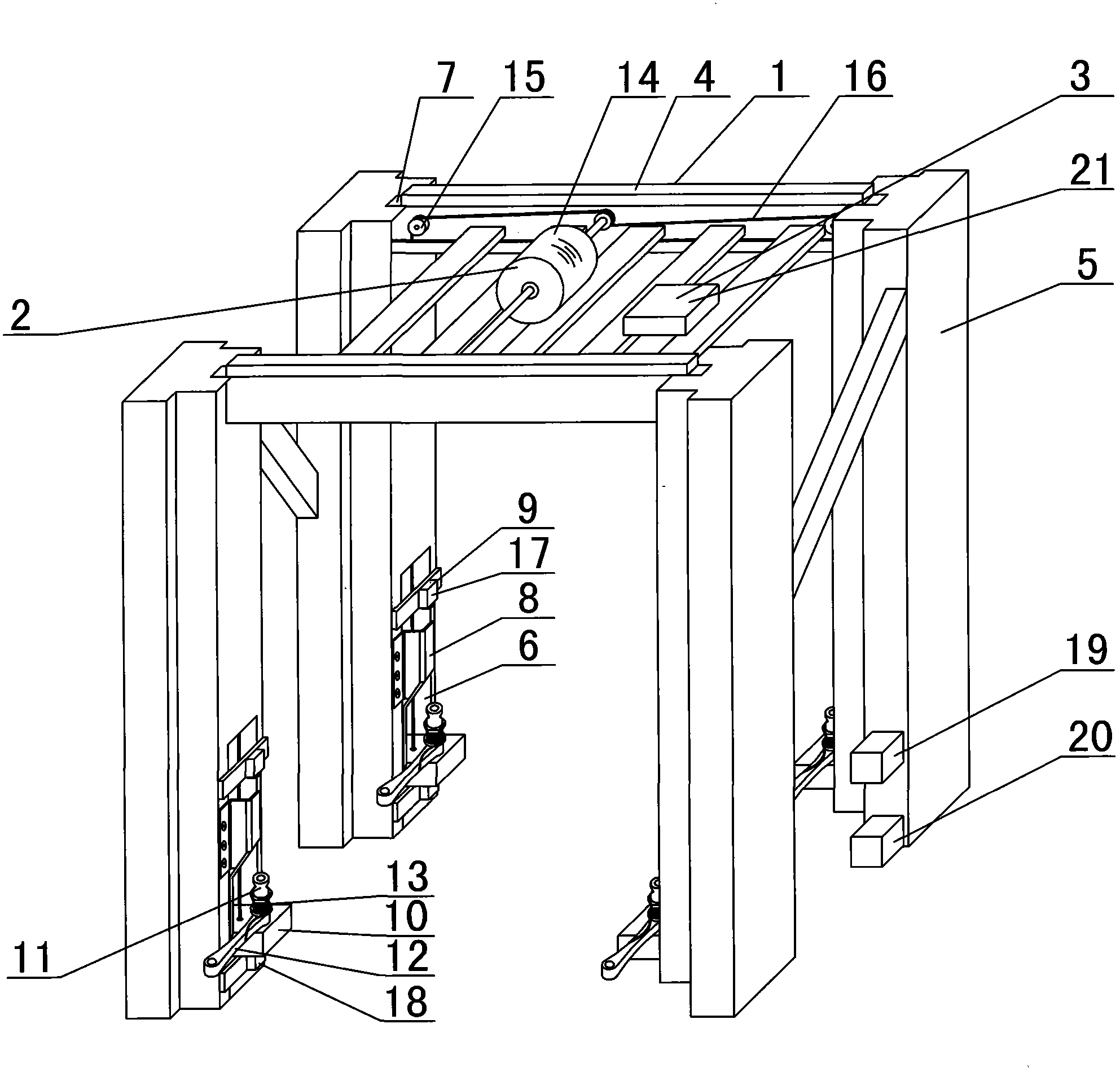
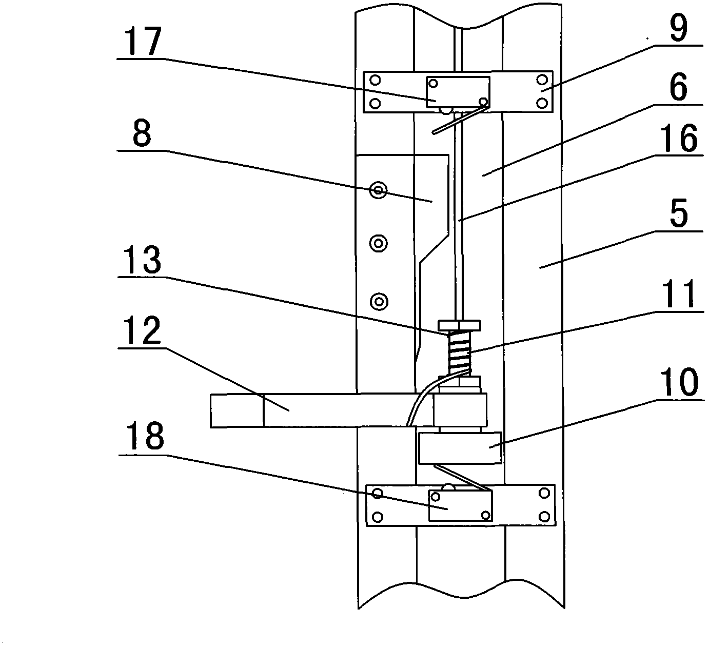
[0019] Embodiment 1: as Figure 1 to Figure 3 As shown, a logistics pallet stacking support includes a support main body 1, a lifting device 2 and a control device 3; the support main body 1 includes a square top support platform 4 and four columns 5, and the four corners of the square top support platform 4 are respectively fixed. There are uprights 5; a chute 6 is vertically provided at the bottom of each upright 5; a vertical through hole 7 communicating with the chute 6 is vertically provided on each upright 5; on the side wall of the chute 6 notch A guide plate 8 is provided; a limit rod 9 is provided in the chute 6 above the guide plate 8; a slider 10 that slides up and down is provided in the chute 6 below the limit rod 9, and one end of the slider 10 is placed in the chute 6 outside, a vertical rotating shaft 11 is fixed on the slide block 10 outside the chute 6, and a support arm 12 for horizontal rotation is provided on the rotating shaft 11; a torsion spring 13 is s...
Embodiment 2
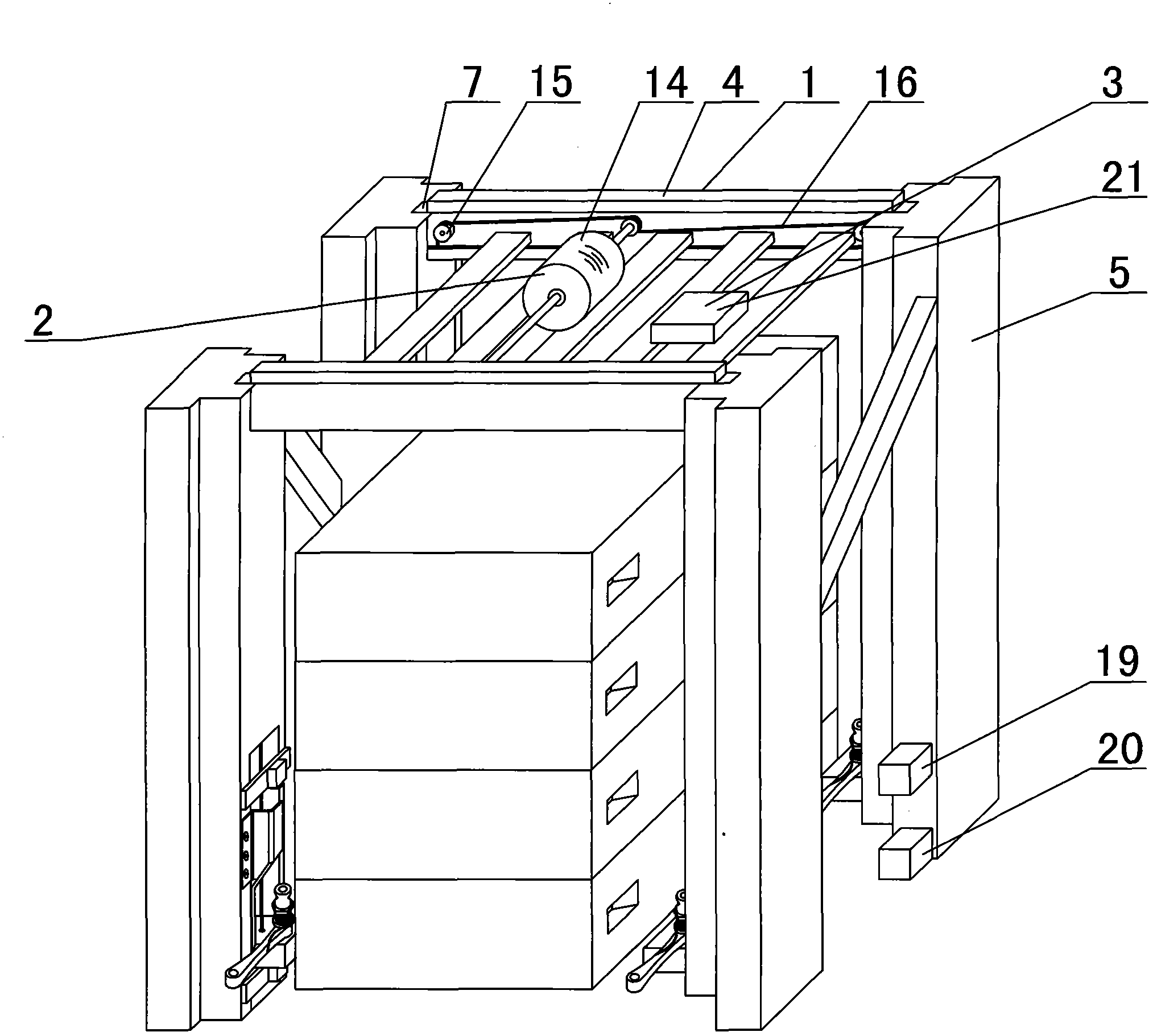
[0024] Embodiment 2: as Figure 4 to Figure 6 A logistics pallet stacking support is shown, which includes a support main body 1, a lifting device 2 and a control device 3. The lifting device 2 includes an air pump 22 and a pneumatic cylinder 23. An air pump 22 is arranged on the upper part of the square top support platform 4. Each column The chute 6 on the 5 is fixedly provided with a pneumatic cylinder 23, and the piston rod 24 of the pneumatic cylinder stretches out or retracts downwards. Connection, the connected pipeline is placed in the corresponding vertical through hole 7; other structures are the same as in Embodiment 1.
[0025] Working process: Push the stacked logistics pallet into the middle of the four columns 5, after the upper infrared photoelectric switch 19 and the bottom infrared photoelectric switch 20 irradiate the pallet, they send a signal to the lifting controller 21, and the lifting controller 21 controls the air pump 22 work, the slide block 10 pres...
Embodiment 3
[0029] Embodiment 3: as Figure 7 with Figure 8 A logistics pallet stacking support is shown, which includes a support main body 1, a lifting device 2, and a control device 3. The lifting device 2 includes a hydraulic pump 25 and a hydraulic cylinder 26. A hydraulic pump 25 is arranged on the top of the square top support platform 4. Each The chute 6 on the root column 5 is fixedly provided with a pneumatic hydraulic cylinder 26, and the hydraulic cylinder piston rod 27 is extended or retracted downwards. The top of the hydraulic cylinder piston rod 27 is fixedly connected with the slide block 10, and each hydraulic cylinder 26 is respectively It is connected with the hydraulic pump 25, and the connected pipeline is placed in the corresponding vertical through hole 7; other structures are the same as in Embodiment 2.
[0030] Working process is identical with embodiment 2.
PUM
 Abstract
Description
Claims
Application Information