Bus braking stop energy recovery device

An energy recovery device and bus technology, applied in the direction of machines/engines, mechanical equipment, mechanisms that generate mechanical power, etc., can solve problems such as energy waste, injury, and damage to brake components, so as to ensure ride comfort and avoid Effect of waste and vibration reduction

Inactive Publication Date: 2013-08-21
SHANGHAI UNIV OF ENG SCI
View PDF5 Cites 3 Cited by
  • Summary
  • Abstract
  • Description
  • Claims
  • Application Information

AI Technical Summary

Problems solved by technology

Due to the complicated vehicle conditions on urban roads, when parking, the driver often does not have enough time to fully slow down and stop the brakes. The brakes are usually relatively urgent, and passengers are often unable to stand firmly in the compartment due to high inertia, and may even be injured; Simultaneously, rapid braking also causes relatively great damage to the braking components of the vehicle, and greater noise will be generated during braking; in addition, due to the large weight and load of the bus, the kinetic energy of the bus at the time of braking is quite large. , However, the current braking method does not recycle this part of energy well, resulting in a lot of energy waste

Method used


Image

  • Bus braking stop energy recovery device
  • Bus braking stop energy recovery device
  • Bus braking stop energy recovery device

Examples


Embodiment Construction

[0039] The present invention will be further described below in conjunction with accompanying drawing.

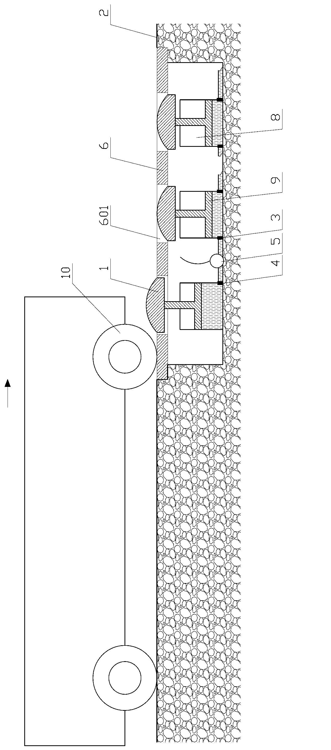
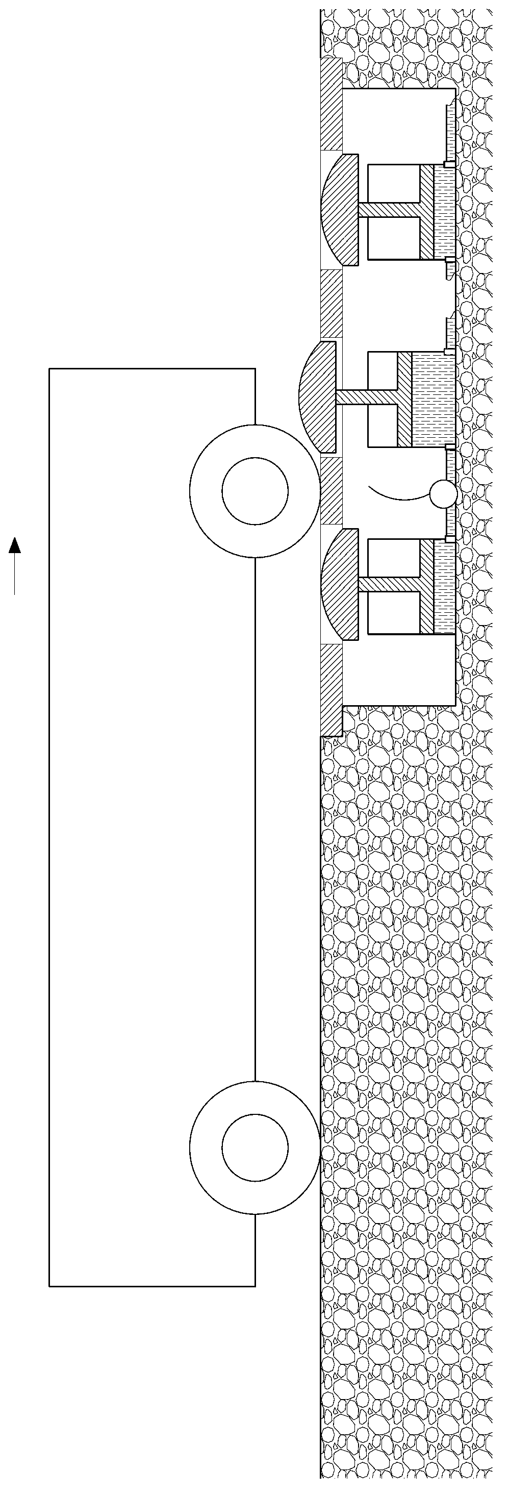
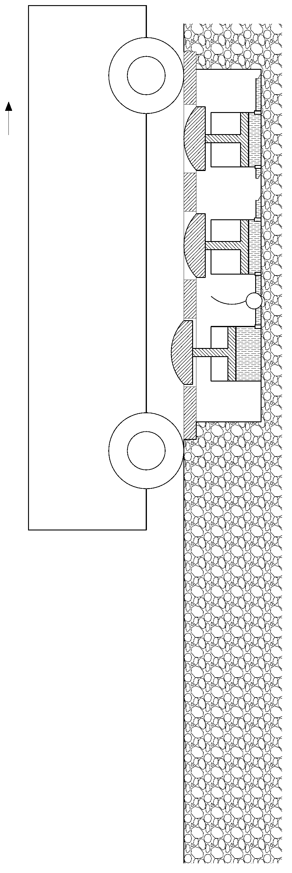
[0040] On the road surface 2 of the bus parking area, two parallel long strip tunnels are set up along the traveling direction of the bus. The tunnels are stepped pits. Each tunnel is covered with a movable cover plate 6, and the outer edge of the cover plate 6 is placed in the tunnel. On the step surface, its top is flush with the road surface 2, and three through holes 601 of equal size are arranged side by side on each cover plate 6, and the positions of the through holes 601 on the two cover plates 6 are the same, as Figure 5 shown.

[0041] A hydroelectric generator 5, a control unit ECU, a storage battery 7 and three water tanks 8 are arranged in each tunnel. The water tanks 8 are located below the through holes 601 and correspond to the through holes 601 one by one. Other components are located in the pit bottom space between the water tanks 8. inside, such as Fi...


PUM


Abstract

Disclosed is a bus braking stop energy recovery device. On a road of an area where a bus stops, two rectangular pits are arranged according to wheel base of the bus, a hydraulic power generator, an ECU (electronic control unit), a storage battery, multiple water tanks, a water pipe and the like are arranged in each pit, a piston is arranged in each water tank, each piston rod penetrates through the top of the corresponding water tank in a vertical upwards manner, and top ends of the water tanks are connected with road pressure discs which vertically move up and down along with the pistons. The device has two states including a standby state and a working state, in the standby state, along the traveling direction of the bus, the first pressure disc is positioned at an ascending high position, other pressure discs are positioned at descending low positions; and in the working state, along the traveling direction of the bus, the pressure disc that the bus is about to press is positioned at the ascending high position, and other pressure discs are positioned at the descending low positions. The bus braking stop energy recovery device can effectively assist a vehicle in speed reduction at a stop area to enable the vehicle to be stable in speed reduction so as to reduce vibratory sensation and guarantee riding comfortableness; and by the bus braking stop energy recovery device, kinetic energy of the bus can be effectively converted into electric energy, so that energy conservation and environment protection are realized.

Description

technical field [0001] The invention relates to the field of public transportation, in particular to the stopping and stopping of buses. Background technique [0002] A bus refers to a motor vehicle that follows a fixed route on an urban road, with or without a fixed shift time, and carries passengers. It is generally rectangular in shape, and the number of carriages varies from 1 to 3. A bus stop area will be set at an appropriate distance to facilitate passengers to get on and off the bus. Buses are the most common form of public transportation. [0003] When the bus is in the parking area, the driver generally relaxes the gas pedal, and the brake pedal is stepped on to realize the stop brake through the stop brake pad. Due to the complicated vehicle conditions on urban roads, when parking, the driver often does not have enough time to fully slow down and stop the brakes. The brakes are usually relatively urgent, and passengers are often unable to stand firmly in the com...

Claims


Application Information

Patent Timeline
Patent Type & Authority Applications(China)
IPC IPC(8): F03G7/00
Inventor 任洪娟罗一平李聪马其华徐彪王汇龙
Owner SHANGHAI UNIV OF ENG SCI
Why Eureka
Try Eureka