Automatic material dividing device with anti-blocking function

A technology of a material distribution device and a driving device is applied in the directions of fuel supply, transportation and packaging, block/powder supply/distribution, etc. Simple, high efficiency of material distribution, strong anti-blocking ability

Active Publication Date: 2013-08-21
NANJING UNIV OF SCI & TECH
View PDF10 Cites 8 Cited by
  • Summary
  • Abstract
  • Description
  • Claims
  • Application Information

AI Technical Summary

Problems solved by technology

CN101613039A proposes a biomass material distribution device with variable inclination and amplitude, which uses vibration to prevent material arching, but each trough of the device needs to be equipped with an independent vibration mechanism, and the implementation process is relatively complicated
CN202828889U proposes a device that utilizes a connecting rod scraper mechanism to realize material distribution. The structure is relatively simple, but it can only realize the material distribution of two feed bins
CN201506615U proposes a kind of screw feeding device, utilizes screw to realize biomass material conveying, adopts shift rod to prevent material clogging, but can only realize the continuous feeding of single outlet
CN101804875A proposes an automatic material distribution device, which uses a semicircular material shifting block to allow materials to be evenly output from the two feed ports, but this device can only adapt to raw materials with regular shapes, and biomass materials are easy to block in this device
CN101955062A proposes a material distributing device of a screw conveyor, but the efficiency of this type of shaft screw conveying loose biomass raw materials is low, and it is easy to block the machine when conveying materials with irregular shapes

Method used


Image

  • Automatic material dividing device with anti-blocking function
  • Automatic material dividing device with anti-blocking function
  • Automatic material dividing device with anti-blocking function

Examples


Embodiment 1

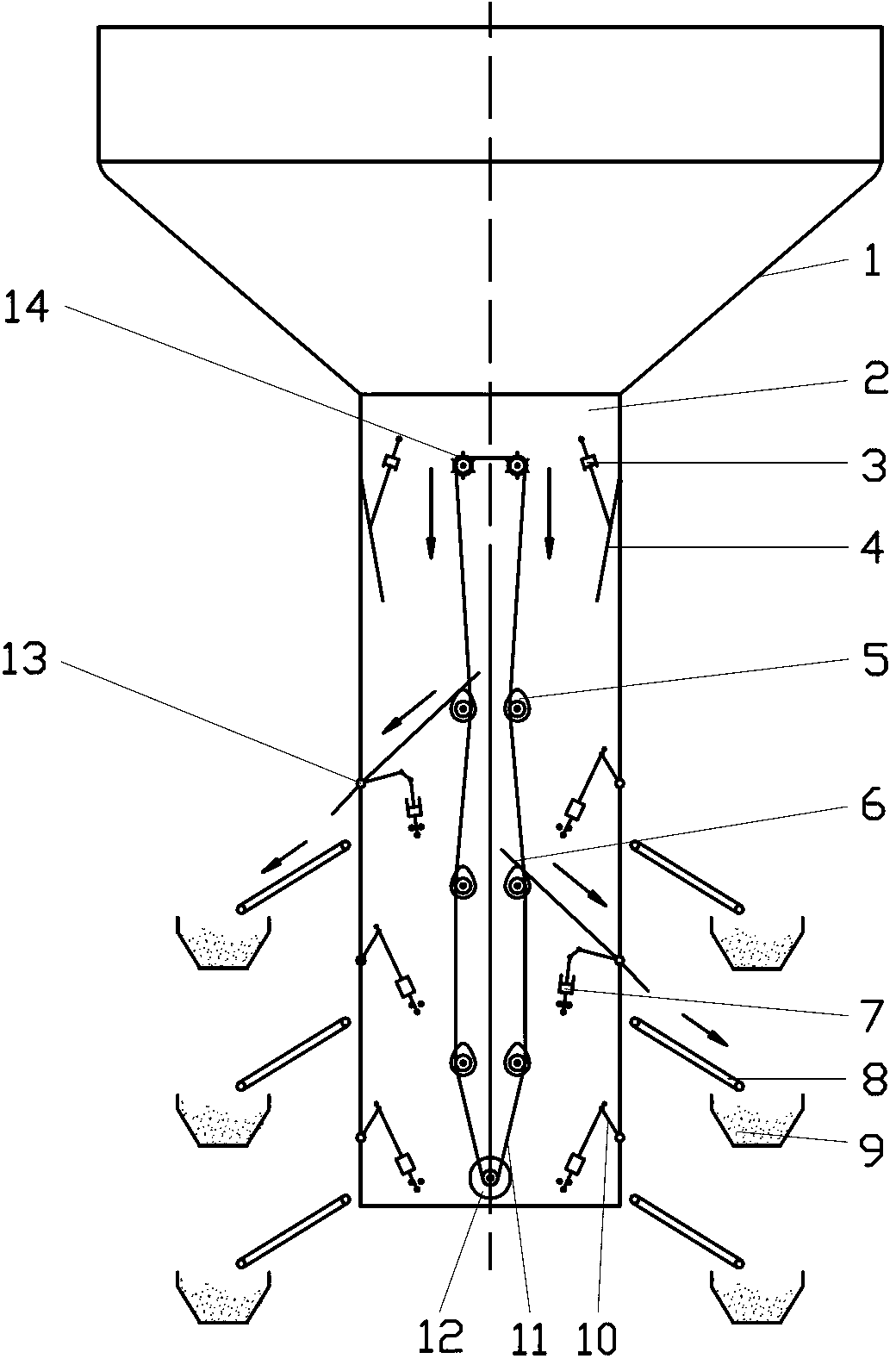
[0026] figure 1 It is a structural schematic diagram of double-side feeding in Embodiment 1 of the automatic material distributing device with anti-blocking function of the present invention.

[0027] In this embodiment, there are 6 distributing units, 3 distributing wheels, and the distance between the distributing wheels and the symmetrical center of the distributing box is 1.5 d, and the distributing units and distributing wheels are arranged symmetrically on both sides of the distributing box . After the required feeding equipment is determined, the driving device of the material distribution plate (in this embodiment, the driving device is a cylinder) 7 respectively opens the corresponding material distribution plate 6 (both sides feed, one material distribution plate is opened on each side, and the rest are closed) After the action of the material distribution plate is completed, the driving device of the material baffle (in this embodiment, the driving device is a cyli...

Embodiment 2

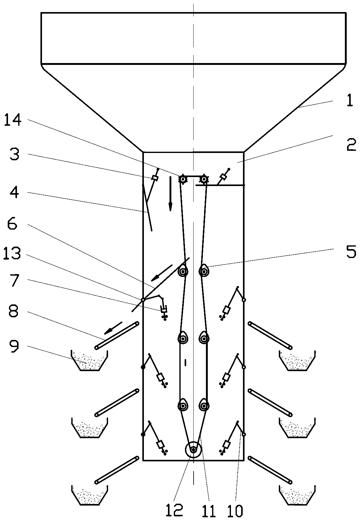
[0031] Figure 4 It is a structural schematic diagram of double-side feeding in Embodiment 2 of the automatic material distributing device with anti-blocking function of the present invention.

[0032]In this embodiment, there are 4 distributing units, 2 distributing wheels, and the distance between the distributing wheels and the symmetrical center of the distributing box is 1.7 d, and the distributing units and distributing wheels are arranged symmetrically on both sides of the distributing box . After the required feeding equipment is determined, the driving device of the material distribution plate (in this embodiment, the driving device is a cylinder) 7 respectively opens the corresponding material distribution plate 6 (both sides feed, one material distribution plate is opened on each side, and the rest are closed) After the action of the material distribution plate is completed, the driving device of the material baffle (in this embodiment, the driving device is a cyli...

Embodiment 3

[0034] Figure 7 It is a structural schematic diagram of double-side feeding in Embodiment 3 of the automatic material distributing device with anti-blocking function of the present invention.

[0035] In this embodiment, there are 8 distributing units, 4 distributing wheels, and the distance between the distributing wheels and the symmetrical center of the distributing box is 2 d, and the distributing units and distributing wheels are arranged symmetrically on both sides of the distributing box . After the required feeding equipment is determined, the driving device of the material distribution plate (in this embodiment, the driving device is a cylinder) 7 respectively opens the corresponding material distribution plate 6 (both sides feed, one material distribution plate is opened on each side, and the rest are closed) After the action of the material distribution plate is completed, the driving device of the material baffle (in this embodiment, the driving device is a cylin...


PUM


Abstract

The invention discloses an automatic material dividing device with an anti-blocking function. A storage hopper is arranged at the top end of a material dividing box. A material blocking board is arranged at the lower end of a connecting part of the storage hopper and the material dividing box. Material stirring wheels are arranged at the upper end near a closing position of the material blocking board. The material blocking board is connected with a material blocking board driving device. Material dividing units are symmetrically arranged on two sides of the material dividing box. Each set of material dividing units comprises a cam mechanism, a material dividing board, a material dividing board dividing device, a conveyor belt and a small storage hopper. Positions of the cam mechanisms correspond to positions of the material stirring wheels. Each material dividing board is arranged on one side, near a box body of the material dividing box, of each cam mechanism. The material dividing board driving devices are connected with the material dividing boards. An opening is formed in a position, corresponding to the material dividing boards, of the material dividing box. The material dividing boards are arranged on rotary shafts arranged at the lower end of the opening of the material dividing box. The conveyor belts and the small storage hoppers are arranged around the opening. A variable frequency motor is arranged at the bottom end of the material dividing box, and is connected with the cam mechanisms and the material stirring wheels through transmission chains. A material storage function and the anti-blocking function are combined, and the automatic material dividing device with the anti-blocking function has the advantages of being capable of dividing materials continuously, high in efficiency and strong in anti-blocking ability.

Description

technical field [0001] The invention belongs to the technical field of conveying and distributing biomass messy and loose raw materials, in particular to an automatic distributing device with an anti-blocking function. Background technique [0002] Biomass refers to various organisms formed through photosynthesis, including crop straw, wood and forestry waste, urban and industrial organic waste and animal manure, etc. The biomass energy stored in it is a clean energy. The United Nations Development Program and the World Energy Council have listed it as the first choice for renewable energy. my country is a large agricultural country with abundant straw biomass resources. The "Twelfth Five-Year Plan for Renewable Energy Development" proposes that by 2015, the annual utilization scale of biomass fuel will reach 15 million tons, so the energy utilization of biomass such as straw has received more and more attention. [0003] Biomass densification molding technology has the ad...

Claims


Application Information

Patent Timeline
Patent Type & Authority Applications(China)
IPC IPC(8): F23K3/00B65G47/46
CPCY02P70/10
Inventor 丁武学孙宇夏先飞王拴虎武凯彭斌彬
Owner NANJING UNIV OF SCI & TECH
Why Eureka
Try Eureka