Solar module mounting clamping device

A technology of solar modules and mounting clips, which is applied in the direction of electrical components, semiconductor devices, photovoltaic power generation, etc., can solve problems such as difficult to meet requirements, achieve the effect of increasing bearing capacity, improving load bearing capacity, and preventing damage due to force

Active Publication Date: 2013-08-21
TRINA SOLAR CO LTD
View PDF7 Cites 8 Cited by
  • Summary
  • Abstract
  • Description
  • Claims
  • Application Information

AI Technical Summary

Problems solved by technology

[0002] At present, for frameless modules or double-glass photovoltaic modules, there are many installation methods in the existing technology: the existing frameless modules and thin-film modules are mainly installed with four-point clamping, the back of the module is glued to the back beam, and the frame structure is added around the module. In order to reduce the cost of material installation, a four-point clamping structure is generally adopted. At present, many thin-film components are preferably installed with a four-point clamping structure. In this installation method, small-sized components can meet the relevant mechanical load requirements in the code, but for large-scale sizes, there is no Frame components or double-glass photovoltaic components are difficult to meet the requirements

Method used


Image

  • Solar module mounting clamping device
  • Solar module mounting clamping device
  • Solar module mounting clamping device

Examples


Embodiment Construction

[0025] In order to make the content of the present invention easier to understand clearly, the present invention will be described in further detail below according to specific embodiments in conjunction with the accompanying drawings,

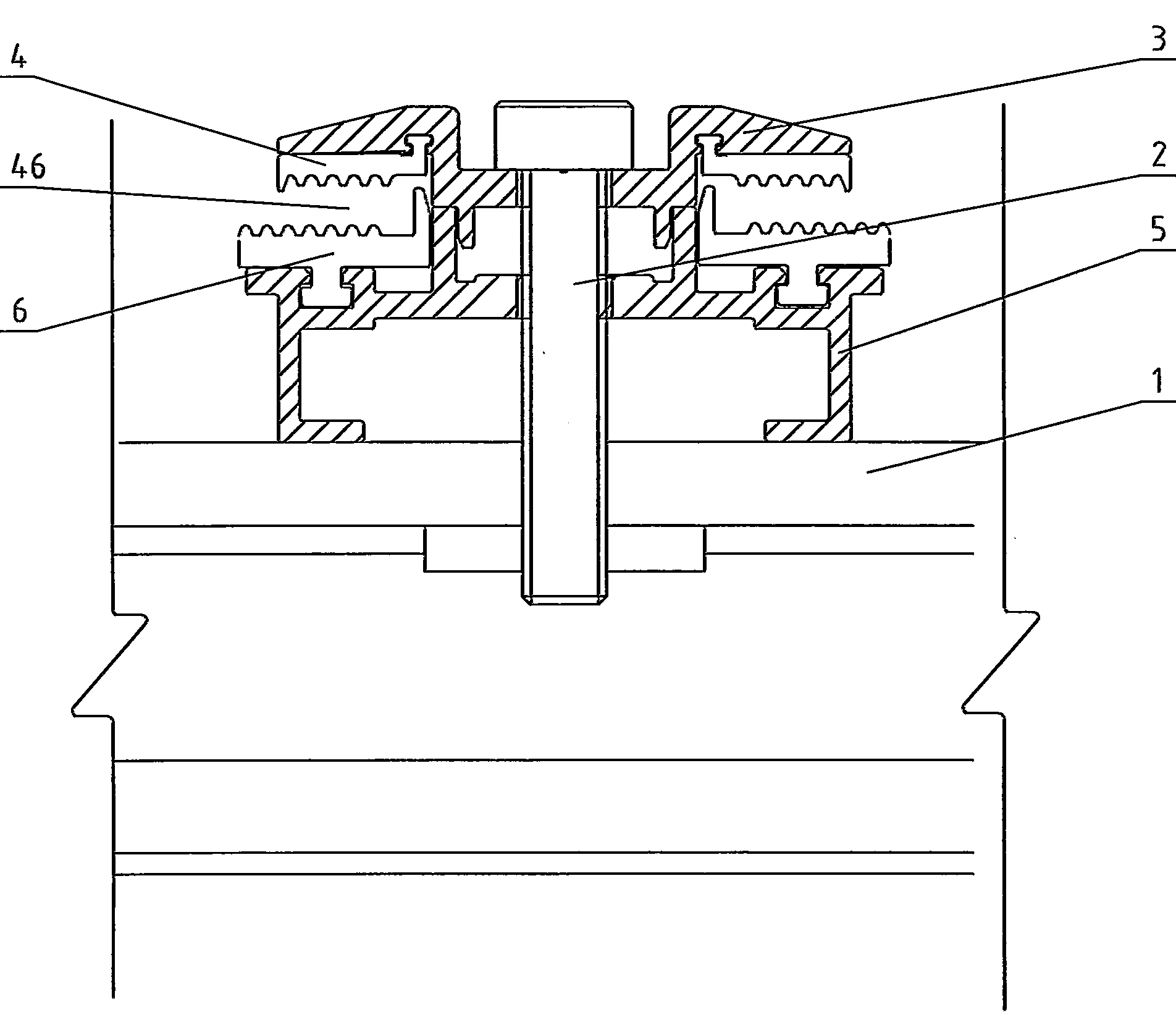
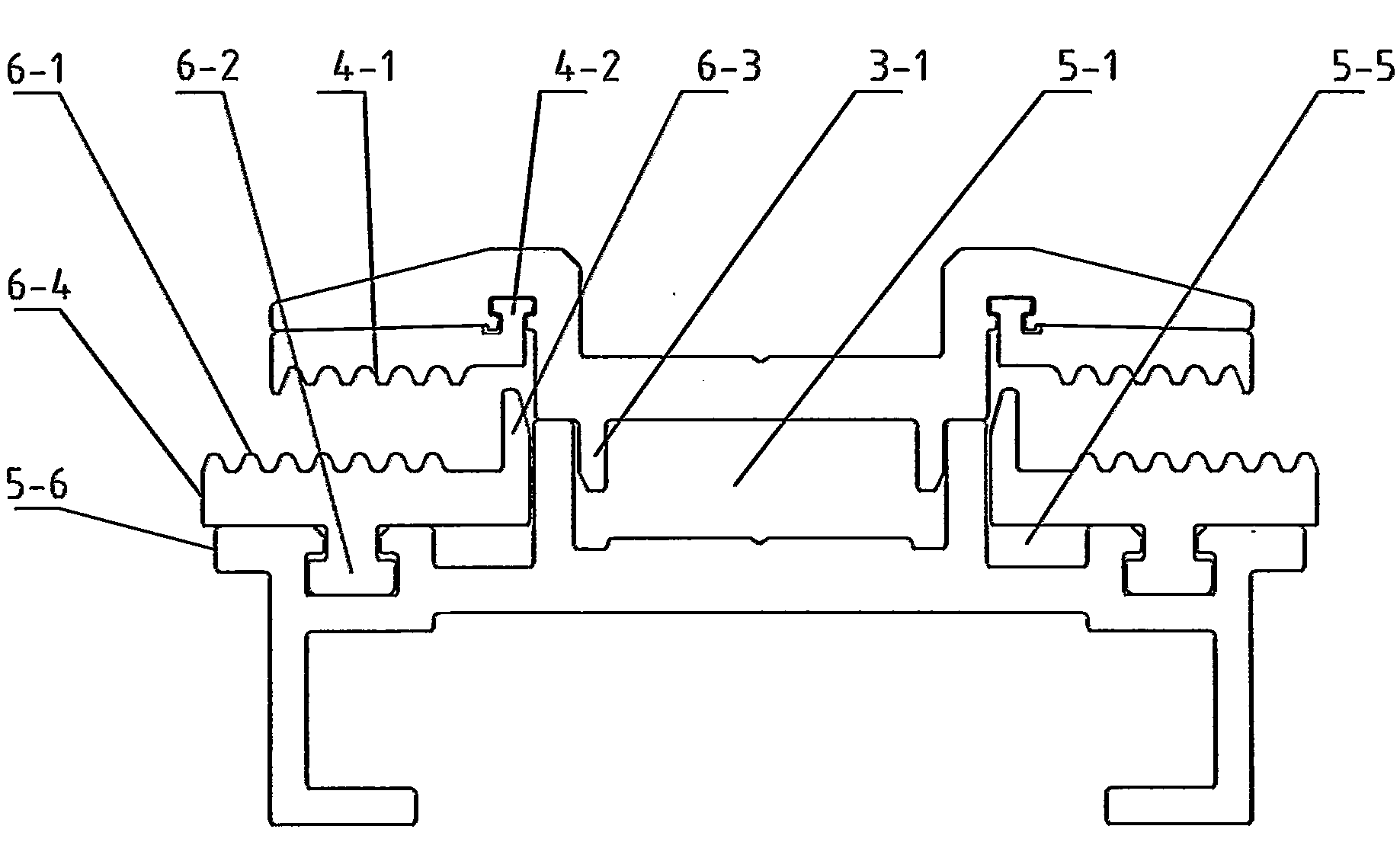
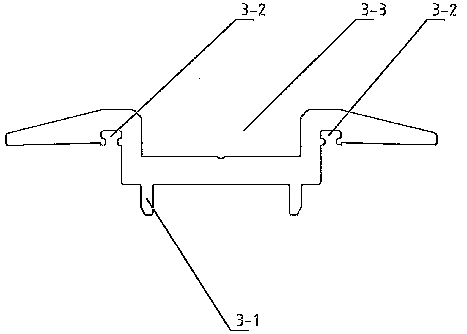
[0026] Such as Figure 1~4 As shown, a solar module installation and clamping device includes a bracket 1, a connecting screw 2, an upper pressing block 3, an upper rubber pad 4, a pressing block seat 5 and a lower rubber pad 6, and the connecting screw 2 passes through the upper pressing block 3 After being fixedly connected with the support 1 with the press block seat 5, the upper rubber pad 4 is clamped on the upper press block 3, the lower rubber pad 6 is clamped on the press block seat 5, and the upper rubber pad 4 has a clamping surface 4-1, The lower rubber pad 6 has a bearing surface 6-1, and a clamping groove 46 for clamping the solar module is formed between the clamping surface 4-1 and the bearing surface 6-1. The bottom end of the...


PUM


Abstract

The invention discloses a solar module mounting clamping device which comprises a support, a connecting screw rod, an upper pressing block, an upper rubber pad, a pressing block seat and a lower rubber pad. The connecting screw rod penetrates through the upper pressing block and the pressing block seat and then is fixedly connected with the support, the upper rubber pad is mounted on the upper pressing block in a clamping mode, the lower rubber pad is mounted on the pressing block seat in a clamping mode, the upper rubber pad is provided with a clamping face, the lower rubber pad is provided with a bearing face, and a clamping groove used for clamping a solar module is formed between the clamping face and the bearing face. A positioning groove is formed in the pressing block seat, a positioning rib set is arranged at the bottom end of the upper pressing block, and the positioning rib set is inserted in the positioning groove and matched with the positioning groove to achieve guiding and positioning. By means of the solar module mounting clamping device, the load bearing ability for mounting the solar module can be improved, and the solar module mounting clamping device is suitable for large-size solar modules.

Description

technical field [0001] The invention relates to a solar module installation and clamping device, which belongs to the technical field of solar battery module installation. Background technique [0002] At present, for frameless modules or double-glass photovoltaic modules, there are many installation methods in the prior art: the installation structure of existing frameless modules and thin-film modules is mainly four-point clamping, the back of the module is glued to the back beam, and the frame structure is added around the module. In order to reduce the cost of material installation, a four-point clamping structure is generally adopted. At present, many thin-film components are preferably installed with a four-point clamping structure. In this installation method, small-sized components can meet the relevant mechanical load requirements in the code, but for large-scale sizes, there is no Frame components or double-glass photovoltaic components are more difficult to meet t...

Claims


Application Information

Patent Timeline
Patent Type & Authority Applications(China)
IPC IPC(8): H01L31/042H02S20/00
CPCY02E10/50
Inventor 高英英蒋阿华付传国束云华徐建美
Owner TRINA SOLAR CO LTD
Why Eureka
Try Eureka