Wheel retaining tool, a manufacturing method thereof and knife flywheel retaining mechanism using wheel retaining tool

A manufacturing method and wheel holding technology, which can be used in manufacturing tools, glass manufacturing equipment, stone processing tools, etc., can solve the problem that the cutter wheel cannot form high-precision scribe lines, etc., to suppress wear resistance or load resistance. Deterioration, load resistance improvement, and wear suppression effects

Active Publication Date: 2011-11-23
MITSUBOSHI DIAMOND IND CO LTD
View PDF6 Cites 5 Cited by
  • Summary
  • Abstract
  • Description
  • Claims
  • Application Information

AI Technical Summary

Problems solved by technology

[0004] On the other hand, tool steel is used for the bearing part of the lower part of the cage, and wear cannot be avoided if compared with parts made of superhard materials.
The rotary support part of the cutter wheel, that is, the outer peripheral surface of the shaft or the inner surface part of the shaft hole of the cutter wheel is also worn due to the rotational friction caused by repeated use. Even if the cutter wheel and the shaft are formed of superhard materials, the final would exceed the tolerance
If there is a gap between the bearing part of the lower part of the holder or the shaft hole of the cutter wheel and the shaft due to wear, the perpendicularity of the cutter wheel will be damaged and it will become impossible to form high-precision scribed lines

Method used


Image

  • Wheel retaining tool, a manufacturing method thereof and knife flywheel retaining mechanism using wheel retaining tool
  • Wheel retaining tool, a manufacturing method thereof and knife flywheel retaining mechanism using wheel retaining tool
  • Wheel retaining tool, a manufacturing method thereof and knife flywheel retaining mechanism using wheel retaining tool

Examples


Embodiment Construction

[0056] Hereinafter, details of the present invention will be described in detail based on drawings showing its embodiment, wherein:

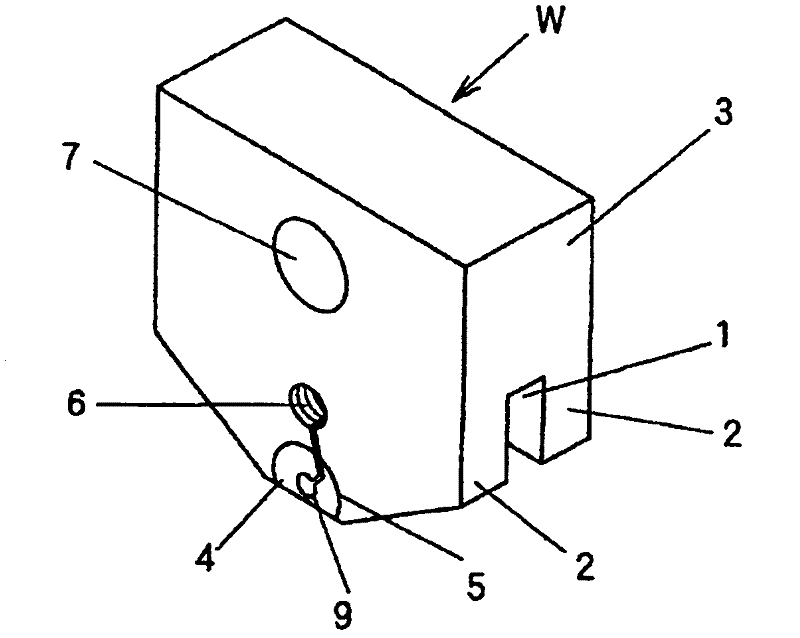
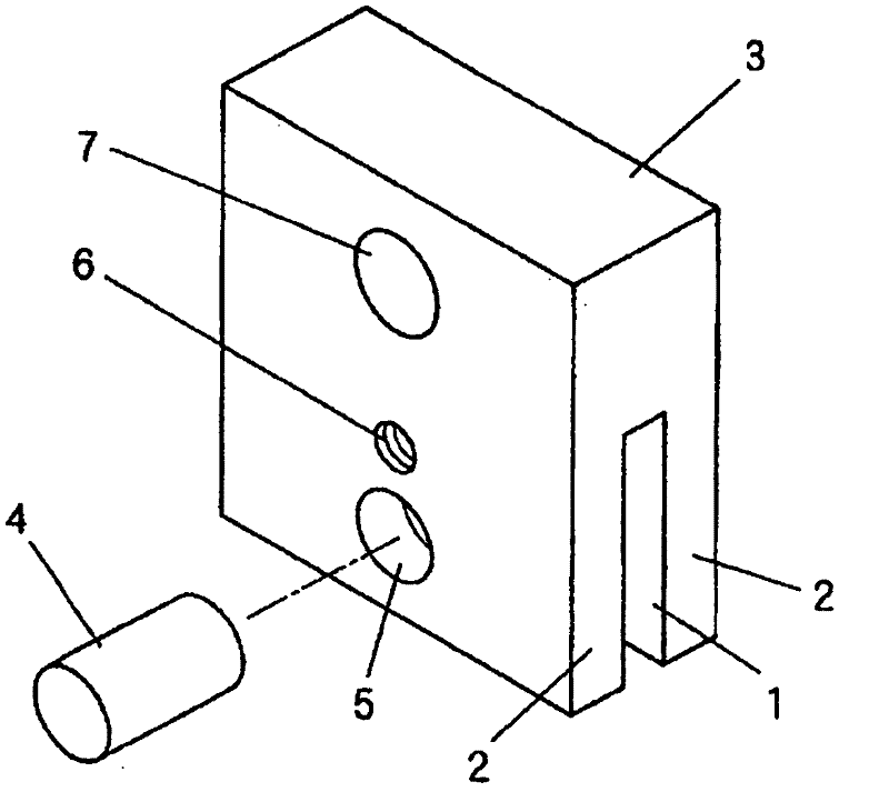
[0057] figure 1 In order to show a perspective view of the wheel holder W manufactured by the manufacturing method of the present invention, the following Figure 7 (d) shows its profile. This wheel holder W is provided with a downwardly opening groove 1 which accommodates a cutter wheel A which will be described later, and a holder main body 3 provided with left and right supporting parts 2 facing each other across the groove 1 . A cylindrical body 4 made of a superhard material (sintered diamond or cemented carbide) is attached to the support part 2 so as to penetrate the support part 2 (partially cut off). In addition, a pin insertion hole 9 is formed in the axial center portion of the cylindrical body 4 by wire electric discharge machining.

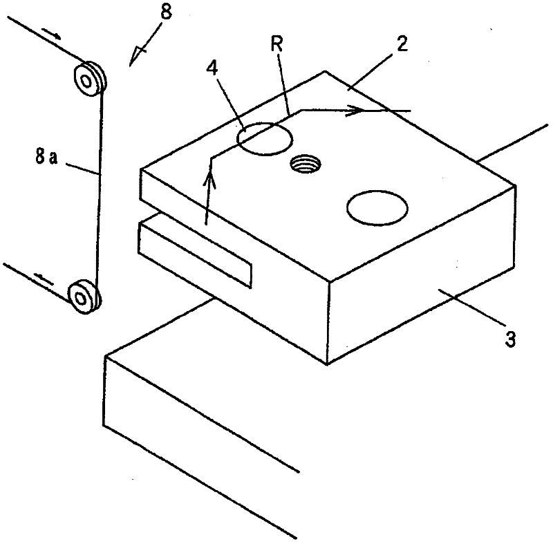
[0058] The following is based on Figure 2-Figure 7 The steps of the production method of the p...


PUM


Abstract

The invention provides a wheel retaining tool having a high rotation precision and an elongated life and a manufacturing method thereof. The method for manufacturing the retaining tool includes steps of: processing the supporting parts 2 which are opposite leftward and rightward with a groove 1 as an interval, a cylindrical installing hole 5 formed by running through the left and right supporting parts 2 and a metallic retaining tool body 3 of a shield installing hole 6 in parallel with the cylindrical installing hole 5; installing a cylinder 4 made of the superhard material in the cylindrical installing hole 5 of the retaining tool body 3; enabling a wire 8a of a wire discharge processing machine 8 to pass through the shield installing hole 6 and moving from the shield installing hole 6 to the cylinder 4 and processing a pin insertion hole 9 at an axle center part of the cylinder 4 in a discharge processing way; and cutting off a middle part of the cylinder 4 in the groove 1 to process a gap 10 placing the knife flywheel A.

Description

technical field [0001] The present invention relates to a wheel holder (also referred to as a cutter wheel holder) for holding a cutter wheel when the cutter wheel is rotated for scribing on a brittle material substrate. Background technique [0002] Generally, when cutting glass substrates, ceramic substrates, semiconductor wafers, etc., the wheel holder is installed on the scribing head of the scribing device, and the cutter wheel held by the wheel holder is pressed against the brittle material substrate while scribing. A predetermined line is run to form a score line. Thereafter, the substrate is broken by bending along the formed scribe line with a break bar or the like. [0003] A wheel holder for holding a cutter wheel is described in Patent Document 1, for example. In the usage example shown in this document, a shaft (cutter pin) supported by a bearing portion (pin insertion hole) formed at the lower portion of the holder is inserted through the shaft hole of the cu...

Claims


Application Information

Patent Timeline
Patent Type & Authority Applications(China)
IPC IPC(8): B28D7/00B28D1/22B28D5/00C03B33/02
CPCB23H7/02B23P15/00B28D7/04C03B33/027
Inventor 阪口良太辻淳一宫川清一
Owner MITSUBOSHI DIAMOND IND CO LTD
Why Eureka
Try Eureka