A kind of wind power generation device

A wind power generation device and wind power technology, which is applied to electromechanical devices, wind turbines, and wind turbines at right angles to the wind direction, etc., can solve the problems of poor typhoon resistance performance of wind power generation devices, many wind power generation device components, and low generator efficiency. , to achieve the effect of improving anti-typhoon performance, good heat dissipation effect and efficiency improvement

Inactive Publication Date: 2016-12-28
卢子政
View PDF4 Cites 0 Cited by
  • Summary
  • Abstract
  • Description
  • Claims
  • Application Information

AI Technical Summary

Problems solved by technology

[0002] With the development of science and technology and the development of new energy sources, various wind power generation devices are more and more widely used. The existing wind power generation devices include fan type power generation devices and rotary drum type power generation devices. The structure is composed of the central shaft of the blade rotor to drive the generator (such as Figure 1-2 shown), Figure 1-2 What is shown is a drum-type power generation device using a traditional generator. This power generation device has the following disadvantages: First, the traditional generator and the wind blade drum are two parts, and the wind power generation device formed after the two are assembled has many parts. The cost is high; secondly, the traditional generator has low efficiency and poor cooling effect; thirdly, the traditional wind power generation device has poor anti-typhoon performance, and the position of the connecting shaft between the traditional generator and the wind blade rotor is prone to breakage accidents when encountering a typhoon; other Fourth, the traditional permanent magnet generator has a cogging effect, so the starting force is relatively large, so it cannot work at low wind speeds, and requires high wind speeds to drive the work

Method used


Image

  • A kind of wind power generation device
  • A kind of wind power generation device
  • A kind of wind power generation device

Examples


Embodiment Construction

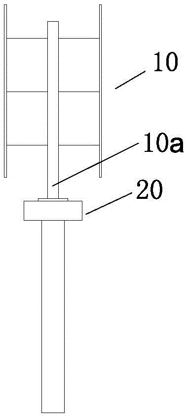
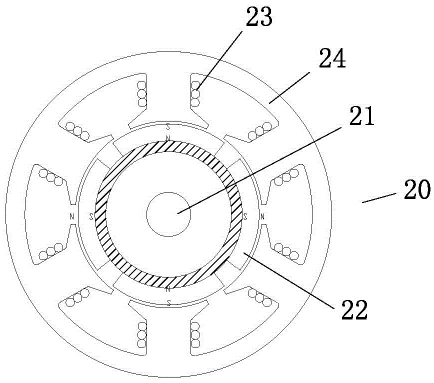
[0029] Such as Figure 1-2 Shown is the cylindrical wind power generation device in the prior art and the cross-sectional view of the existing generator, which can be obtained from figure 1 It can be seen that the existing wind power generation device is formed by connecting two parts of the fan blade drum 10 and the generator 20, and the central rotating shaft 10a of the fan blade drum 10 is connected with the input shaft of the generator 20 to drive the generator to work and generate electricity; figure 2 It can be seen that the structure of the existing generator 20 is composed of a central shaft 21 , a rotor formed by several magnets 22 and several group winding coils 23 fixed on the outer ring. The winding coils 23 are wound on the core 24 . The drawbacks of this construction have been pointed out in the background art.

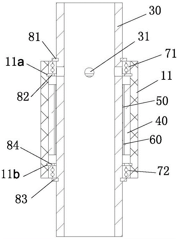
[0030] Figure 3-7 It is an embodiment of the present invention, and it includes: a fixed central shaft 30 and a blade rotor 10, the middle of the bl...


PUM


Abstract

The invention relates to a wind power generation device which is provided with an integrated generation device. The wind power generation device comprises a fixed center shaft and a fan blade rotary drum. A center sleeve is arranged in the middle of the fan blade rotary drum. A plurality of blades used for collecting wind power are arranged outside the center sleeve. The fan blade rotary drum is movably sleeved on the fixed center shaft through the center sleeve in a spaced mode so that the fan blade rotary drum can freely rotate relative to the fixed center shaft. The fixed center shaft and the center sleeve are all made of permeability magnetic materials. Permanent magnets are arranged on one wall face, corresponding to the outer wall of the fixed center shaft, of the inner wall of the center sleeve. Winding coils corresponding to the permanent magnets are arranged on the other wall face, corresponding to the inner wall of the center sleeve, of the outer wall of the fixed center shaft. The wind power generation device is more compact in structure through adoption of a perpendicular axial wind power generation system of a novel motor, enables cost to be reduced through adoption of the integrated design, and has the advantages of being high in structural rigidity, better in heat dissipation effects, long in service life, fewer in the number of parts, and simple in structure.

Description

technical field [0001] The invention relates to the technical field of wind power generation equipment, in particular to a wind power generation device with an integrated power generation device. Background technique [0002] With the development of science and technology and the development of new energy sources, various wind power generation devices are more and more widely used. The existing wind power generation devices include fan type power generation devices and rotary drum type power generation devices. The structure is composed of the central shaft of the blade rotor to drive the generator (such as Figure 1-2 shown), Figure 1-2 What is shown is a drum-type power generation device using a traditional generator. This power generation device has the following disadvantages: First, the traditional generator and the wind blade drum are two parts, and the wind power generation device formed after the two are assembled has many parts. The cost is high; secondly, the trad...

Claims


Application Information

Patent Timeline
Patent Type & Authority Patents(China)
IPC IPC(8): H02K7/18F03D3/00
CPCY02E10/74
Inventor 卢子政孙国伟孙金波
Owner 卢子政
Why Eureka
Try Eureka