A fixed stator eddy current retarder
A fixed, retarder technology, applied in the direction of asynchronous induction clutch/brake, etc., can solve the problems of complex winding of the retarder, low magnetic field utilization, small braking torque, etc., to avoid thermal failure of the brake , Improve the braking safety performance, the effect of large braking torque
- Summary
- Abstract
- Description
- Claims
- Application Information
AI Technical Summary
Problems solved by technology
Method used
Image
Examples
Embodiment Construction
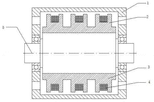
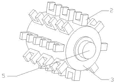
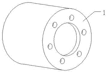
[0015] Such as figure 1 As shown, a stator fixed eddy current retarder according to the present invention includes an outer rotor 1, a U-shaped stator yoke 2, an inner stator 3, an excitation coil 4 and a stator shaft 5. See image 3 , The outer rotor 1 has a hollow cylindrical structure and is fixed on the input end of the rear axle or the output end of the gearbox through a connecting flange. An inner stator 3 is coaxially sleeved inside the outer rotor 1, and the center of the inner stator 3 is coaxially and fixedly connected to the stator shaft 5. The two ends of the stator shaft 5 extend out of the two ends of the outer rotor 1, and both ends of the outer rotor 1 are supported by bearings. On the stator shaft 5. The two ends of the stator shaft 5 are connected with the half shaft through a coupling. The inner stator 3 can be designed as a hollow cylindrical structure, and the stator shaft 5 is fixedly sleeved in the central hole of the inner stator 3.
[0016] See again f...
PUM
 Abstract
Description
Claims
Application Information
 - R&D
- Intellectual Property
- Life Sciences
- Materials
- Tech Scout
- Unparalleled Data Quality
- Higher Quality Content
- 60% Fewer Hallucinations
Browse by: Latest US Patents, China's latest patents, Technical Efficacy Thesaurus, Application Domain, Technology Topic, Popular Technical Reports.
© 2025 PatSnap. All rights reserved.Legal|Privacy policy|Modern Slavery Act Transparency Statement|Sitemap|About US| Contact US: help@patsnap.com


