Active upward-pulling circuit of drain electrode open circuit signal

An open-drain, active pull-up technology, applied in the direction of logic circuit coupling/interface, logic circuit connection/interface layout, reliability improvement and modification using field effect transistors, etc.

Inactive Publication Date: 2013-08-21
SUZHOU BATELAB MICROELECTRONICS
View PDF7 Cites 5 Cited by
  • Summary
  • Abstract
  • Description
  • Claims
  • Application Information

AI Technical Summary

Problems solved by technology

However, reducing the pull-up resistor will have an adverse effect on the circuit operation

Method used


Image

  • Active upward-pulling circuit of drain electrode open circuit signal
  • Active upward-pulling circuit of drain electrode open circuit signal
  • Active upward-pulling circuit of drain electrode open circuit signal

Examples


Embodiment Construction

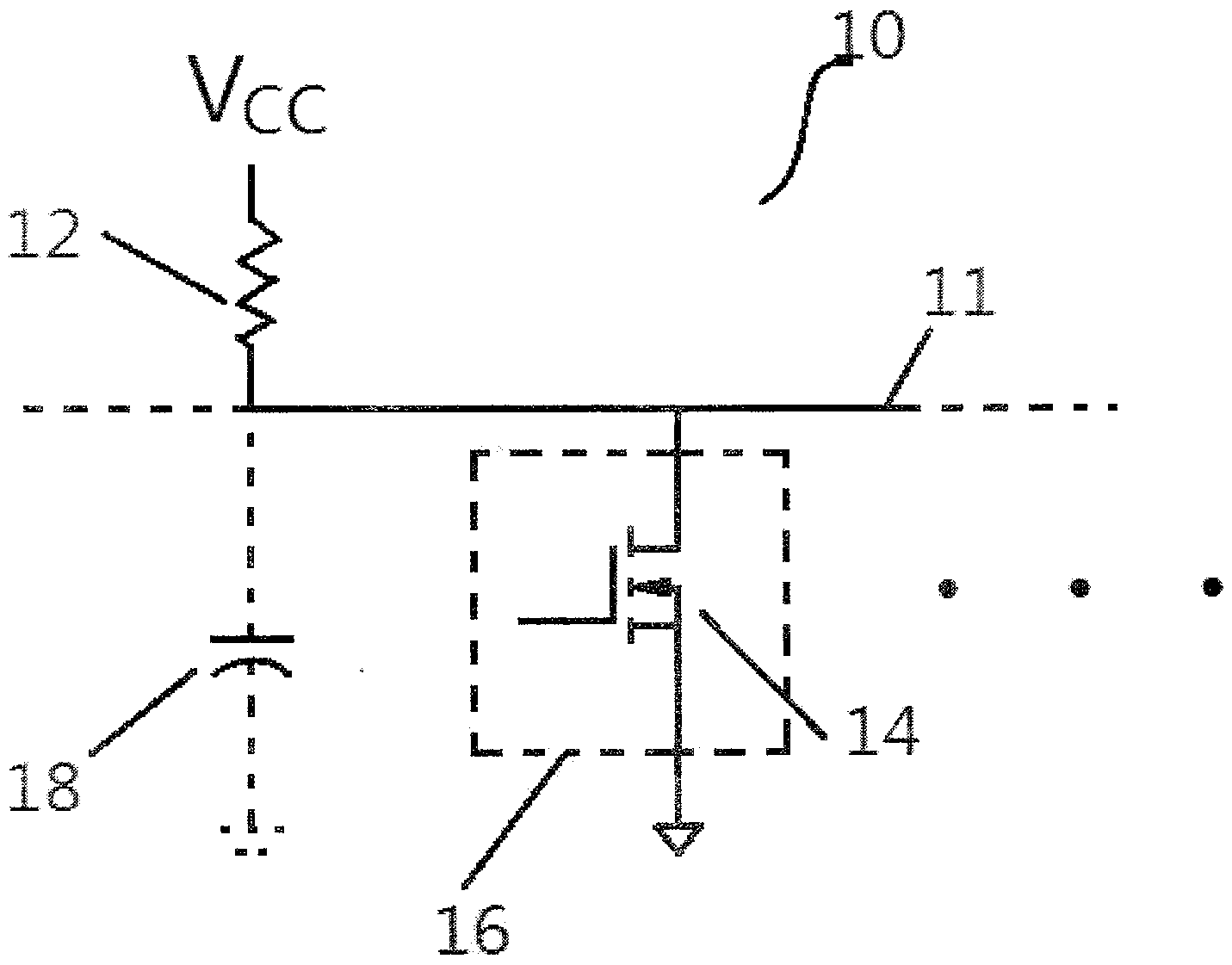
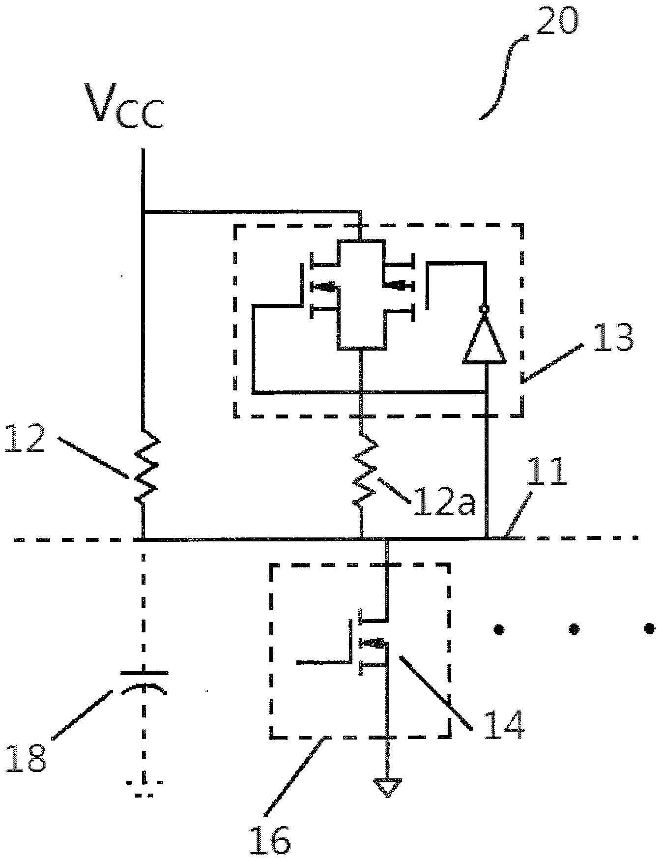
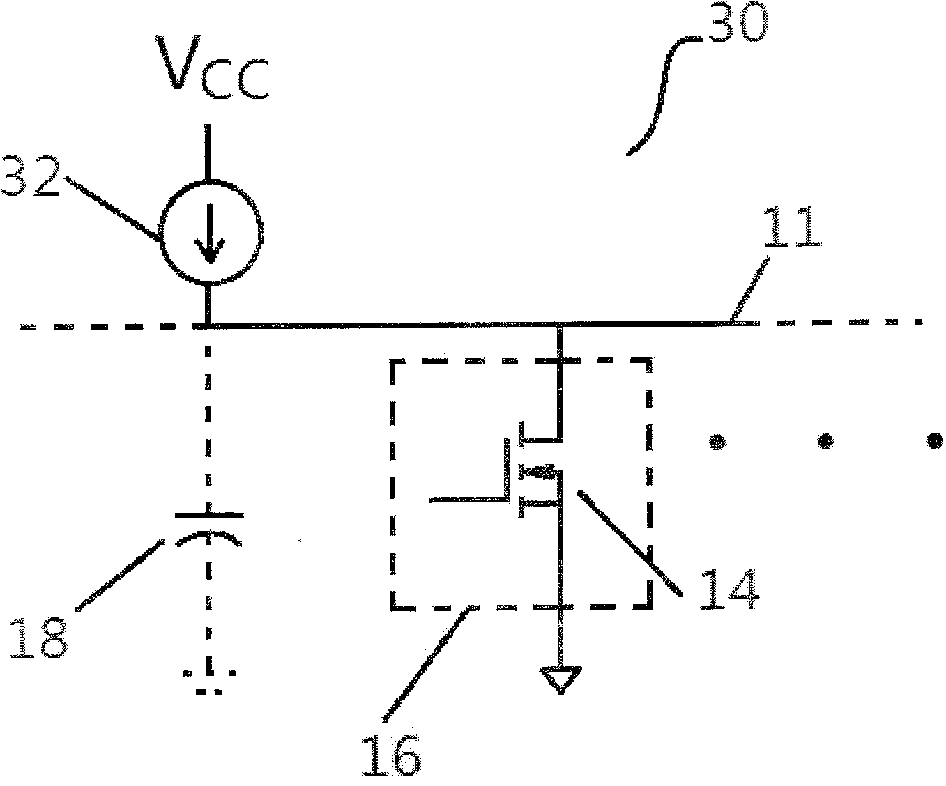
[0025] Figures 1A to 1C is a simplified schematic diagram of a previously known circuit implementing a signal line using an open-drain structure. Device 16 represents a device coupled to signal line 11 and may be anything from an integrated circuit to a computer peripheral. Device 16 includes drive transistor 14 and is ON and OFF controlled by additional circuitry in device 16 (not shown). Optionally, device 16 may include a terminal to control an external drive transistor. Although only one device is connected to signal line 11 in the schematic diagrams in FIGS. 1, 3 and 5, those skilled in the art will understand that there may be multiple devices.

[0026] Capacitor 18 represents the parasitic capacitance connected to signal line 11 , including the stray capacitance of drivers and receivers connected to signal line 11 and coupled to signal line 11 . The main effect of parasitic capacitance 18 , whose value is typically in the order of one hundred picofarads, is to limit ...


PUM


Abstract

The invention discloses an active upward-pulling circuit of a drain electrode open circuit signal and provides a circuit and a method for reducing signal rising time in a signal line of a drain electrode open circuit or a collector electrode opening circuit. Voltage of the signal line is monitored so as to ensure whether the signal line is pulled to be low. If the signal line is not pulled to be low, the voltage of the indicated signal line exceeds a threshold value electrical level, and extra upward-pulling currents are provided. The voltage of the signal line is responded to, and the extra currents are provided gradually. Or, no matter whether the voltage exceeds a threshold or not, all the currents will be provided. The circuit can be used for monitoring the change rate of the voltage of the signal line, and enabling the upward-pulling currents to exist only when the change rate exceeds a positive threshold value level.

Description

technical field [0001] The present invention provides circuits and methods for driving signal lines using open-drain or open-collector circuits to increase switching speed, and more particularly, rate-sensitive, hysteretic, active pull-up circuits and methods. [0002] The term "open drain" will be used broadly in the following description. Although "open drain" may describe the use of field effect transistors, for example MOSFETs can function in this field with other types of transistors, as well as triodes. Therefore, the term open-drain can be understood as a broad concept here, and this term includes open-collector circuits. Further, the present invention does not use only MOSFETs, and such transistors may include other suitable transistors. [0003] Open-drain circuits are widely used in interconnected electronic devices. Open-drain signal lines are used in computer systems and are driven by multiple sources, for example, the interrupt input of a microprocessor. Back...

Claims


Application Information

Patent Timeline
Patent Type & Authority Applications(China)
IPC IPC(8): H03K19/003H03K19/0185
Inventor 李真
Owner SUZHOU BATELAB MICROELECTRONICS
Why Eureka
Try Eureka