Woofer and electronic device applying same

A loudspeaker and bass technology, applied in the fields of woofers and electronic devices, can solve problems such as waste, large magnet size, and excess magnet performance

Inactive Publication Date: 2013-08-21
GOERTEK INC
View PDF3 Cites 24 Cited by
  • Summary
  • Abstract
  • Description
  • Claims
  • Application Information

AI Technical Summary

Problems solved by technology

If a flat diaphragm is used, combined with a voice coil structure (the voice coil needs to be located close to the edge), the large-area diaphragm requires a relatively large voice coil size, which is difficult to wind and easy to deform
In addition, the magnet size of the existing woofer is relatively large, and the thickness of the washer and the basin frame are small when the thinning is applied, the magnetic circuit system is easily saturated, the magnet performance is excessive, resulting in waste, and the cost is high

Method used


Image

  • Woofer and electronic device applying same
  • Woofer and electronic device applying same
  • Woofer and electronic device applying same

Examples


Embodiment 1

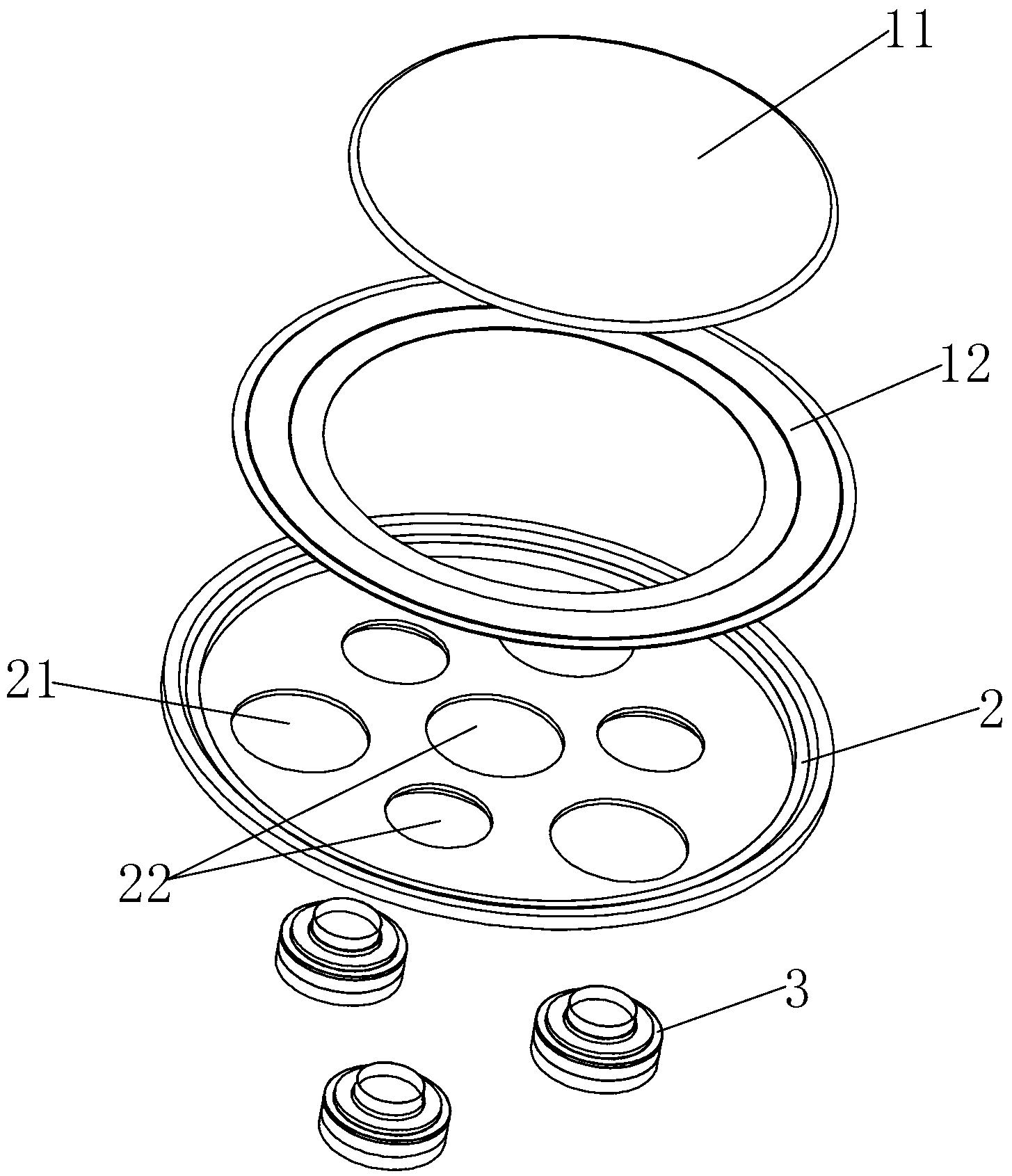
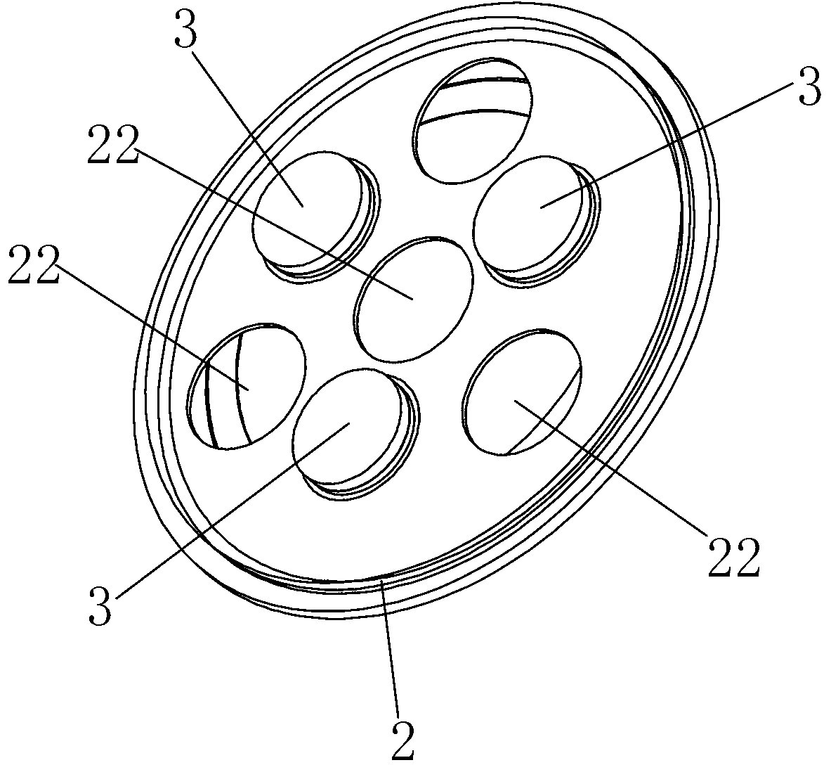
[0031] Such as Figure 1 to Figure 4 As shown, the woofer of the present invention includes a diaphragm and a drive unit combined on one side of the diaphragm, wherein the diaphragm is a circular plate-shaped structure, including a rigid ball top 11 at the center and a flexible dome at the edge. The ring part 12, the ball top 11 and the ring part 12 are fixedly combined by bonding or the like. The loudspeaker of the present invention is a subwoofer, therefore, the area of ​​the diaphragm is relatively large to ensure the low-frequency sound effect of the product. Wherein, the diaphragm includes a plurality of drive units 3 dispersedly arranged, and each drive unit 3 includes a voice coil 31 and a magnetic circuit system for accommodating the voice coil 31 , wherein the voice coil 31 is fixedly combined with the diaphragm. It also includes a housing 2. The housing 2 includes a mounting surface for installing the magnetic circuit system and a side wall located around the mounti...

Embodiment 2

[0038] Such as Figure 6 and Figure 7 As shown, the woofer includes a diaphragm and four drive units 3 combined on the lower side of the diaphragm. Same as the previous embodiment, the diaphragm includes a rigid ball top 11 at the center and a ring portion 12 at the edge. The shell 2' is set corresponding to the drive unit 3, and has four mounting holes 21 for installing the drive unit 3. Similarly, the shell 2' is also provided with sound holes 22 communicating with the outside, and the sound holes 22 are respectively located on the shell 2' and directly opposite The position of the center of the diaphragm and between two adjacent drive units 3 . In this embodiment, the four drive units 3 are located on the same circumference and have the same distance from the center of the diaphragm circle, and the distances between two adjacent drive units 3 are equal, that is, the distance between two adjacent drive units 3 and the center of the circle is equal. The included angle is 90 ...


PUM


Abstract

The invention discloses a woofer comprising a round flat-panel-shaped vibrating diaphragm, the vibrating diaphragm comprises a rigid ball top located at the center position and a ring folding part located at the edge position, and the ball top is of a flat-panel-shaped structure. The woofer further comprises an outer shell, the vibrating diaphragm is combined on the upper lateral face of the outer shell, wherein a plurality of voice coils arranged in a distributed mode are combined on the surface, close to the outer shell, of the vibrating diaphragm, the voice coils drive the vibrating diaphragm to vibrate in a balanced mode, each voice coil corresponds to an independent magnetic circuit system, and the magnetic circuit systems are contained and fixed in the outer shell. According to the structure, the thickness of the woofer is reduced, and therefore the woofer of the structure can be applied to thin-type electronic devices and is favorable for thinning of the electronic devices.

Description

technical field [0001] The invention relates to the field of electroacoustics, in particular to a subwoofer and an electronic device using the subwoofer. Background technique [0002] With the progress of society and the development of technology, in recent years, electronic products such as televisions have become thinner and thinner, and people have higher and higher performance requirements for these electronic products, which also requires the thickness of electronic components that are matched with them to be reduced. Small, performance and consistency improvements. [0003] The woofer is an important electronic component widely used in the above-mentioned electronic products. In thin electronic devices such as LCD TVs and notebook computers, it is required to minimize its thickness on the basis of ensuring the performance of the speaker to meet the needs of thin electronic devices. . [0004] The woofer with the traditional structure usually adopts a cone-shaped cone...

Claims


Application Information

Patent Timeline
Patent Type & Authority Applications(China)
IPC IPC(8): H04R9/06H04R9/02
Inventor 江超杨健斌李志焦其金
Owner GOERTEK INC
Why Eureka
Try Eureka