Check patentability & draft patents in minutes with Patsnap Eureka AI!

Hydraulic automatic tensioner

A hydraulic and tensioner technology, applied in the direction of transmission, belt/chain/gear, mechanical equipment, etc., to achieve the effect of simple assembly

Inactive Publication Date: 2013-08-21
NTN CORP
View PDF6 Cites 4 Cited by
  • Summary
  • Abstract
  • Description
  • Claims
  • Application Information

AI Technical Summary

Problems solved by technology

[0008] However, in the hydraulic automatic tensioner described in Patent Document 1, since it is necessary to inject the working oil twice before and after inserting the plunger into the sleeve, and because when the plunger is inserted into the sleeve, There will be air remaining in the pressure chamber, so exhaust work is required, so there is room for improvement in terms of ease of assembly of the hydraulic automatic tensioner

Method used


Image

  • Hydraulic automatic tensioner
  • Hydraulic automatic tensioner
  • Hydraulic automatic tensioner

Examples


Embodiment Construction

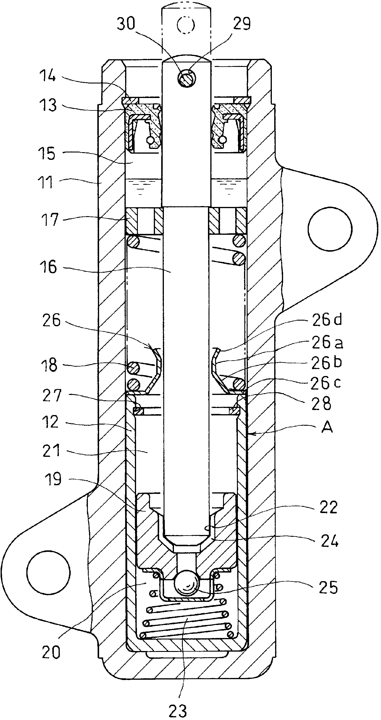
[0043] Embodiments of the present invention will be described below based on the drawings. Such as figure 1 As shown, the hydraulic automatic tensioner related to the present invention has a cylinder 11 installed in the engine block. The cylinder 11 is formed of aluminum alloy and has a bottom, and a valve sleeve 12 is fitted inside. The air valve sleeve 12 is made of steel and has a bottom.

[0044] The upper opening of the cylinder 11 is sealed by incorporating a sealing member 13 formed of an oil seal, and the sealing member 13 is prevented from falling off by a stop ring 14 installed on the inner periphery of the upper end of the cylinder 11, and the sealing member 13 is used to prevent filling into the cylinder 11. The internal working oil leaks to the outside. Furthermore, an air retention portion 15 is provided on the oil surface of the working oil.

[0045] On the push rod 16 that penetrates the sealing member 13 in a slidable manner and is located above the upper ...


PUM


Abstract

A hydraulic damper unit (A) comprising a plunger (19), a plunger spring (23), and a valve sleeve (12), in which the plunger (19) and the plunger spring (23) are mounted, is formed by retaining the plunger (19) by attaching a C-shaped retaining ring (28) for a hole to the inner periphery of the opening end of the valve sleeve (12). The hydraulic damper unit (A), the valve sleeve (12) of which is filled with operating oil, is inserted into a cylinder (11), operating oil is filled into the cylinder (11), and after the return spring (18) and the push rod (16) are mounted, the upper end opening of the cylinder (11) is closed by mounting a seal member (13). Thus, the assembly of the hydraulic automatic tensioner is facilitated.

Description

technical field [0001] The present invention relates to a hydraulic automatic tensioner for maintaining constant tension of a timing belt or an auxiliary machine driving belt in a camshaft driving belt transmission of an internal combustion engine. Background technique [0002] In the camshaft driving belt drive of the internal combustion engine installed in the automobile, the timing belt (hereinafter, simply referred to as the belt) due to the change of the shaft distance caused by the thermal expansion of the internal combustion engine body when the internal combustion engine is running or due to aging stretches, causing the tension in the belt to change. [0003] Therefore, in the above-mentioned belt transmission device, the adjustment force of the hydraulic automatic tensioner is applied to the belt to keep the tension of the belt constant, thereby preventing the generation of abnormal noise or tooth creep due to vibration of the belt. [0004] As the above-mentioned ...

Claims


Application Information

Patent Timeline
Patent Type & Authority Applications(China)
IPC IPC(8): F16H7/08
CPCF16H7/0836F16H2007/0806F16H2007/0859
Inventor 高野武博北野聪
Owner NTN CORP
Features
  • R&D
  • Intellectual Property
  • Life Sciences
  • Materials
  • Tech Scout
  • Unparalleled Data Quality
  • Higher Quality Content
  • 60% Fewer Hallucinations
Learn More