
Ozone and plasma generation using electron beam technology

A plasma and electron beam technology, applied in the field of ozone and plasma generation by electron beam technology, can solve the problems of inability to accurately control electric field interaction, change of reaction efficiency, and limitation of process flexibility

Inactive Publication Date: 2013-08-21
HITACHI ZOSEN CORP
View PDF5 Cites 0 Cited by
  • Summary
  • Abstract
  • Description
  • Claims
  • Application Information

AI Technical Summary

Problems solved by technology

There are some fundamental limitations to generating an electric field in the same chamber that decomposes the input process gas into ozone or plasma
One limitation is that the reacted gas may modify the surface of the chamber such that the way the electric field is generated changes the efficiency of the reaction
The second limitation is that the reacted gases may modify the surfaces of the chamber such that additional unwanted particles are formed
A third limitation is that it is difficult or impossible to precisely control how the electric field interacts with the process gas, limiting process flexibility
Furthermore, conventional approaches have resulted in the ability to only partially control the energy levels of electrons

Method used


Image

  • Ozone and plasma generation using electron beam technology
  • Ozone and plasma generation using electron beam technology
  • Ozone and plasma generation using electron beam technology

Examples


Embodiment Construction

[0025] In order to provide a thorough understanding of the systems and methods described herein, certain exemplary embodiments will now be described, including systems for constructing an ozone generator or plasma generator that An electric field is generated in a chamber separate from the reaction chamber. For purposes of illustration, the systems and methods described herein will be discussed with reference to providing gases to a wafer processing system. However, those of ordinary skill in the art will appreciate that the systems and methods described herein can be appropriately adapted and modified for the application to which they are addressed, and that the systems and methods described herein can be adapted for many suitable applications , and other additions and modifications of the described systems and methods are possible within the scope thereof.

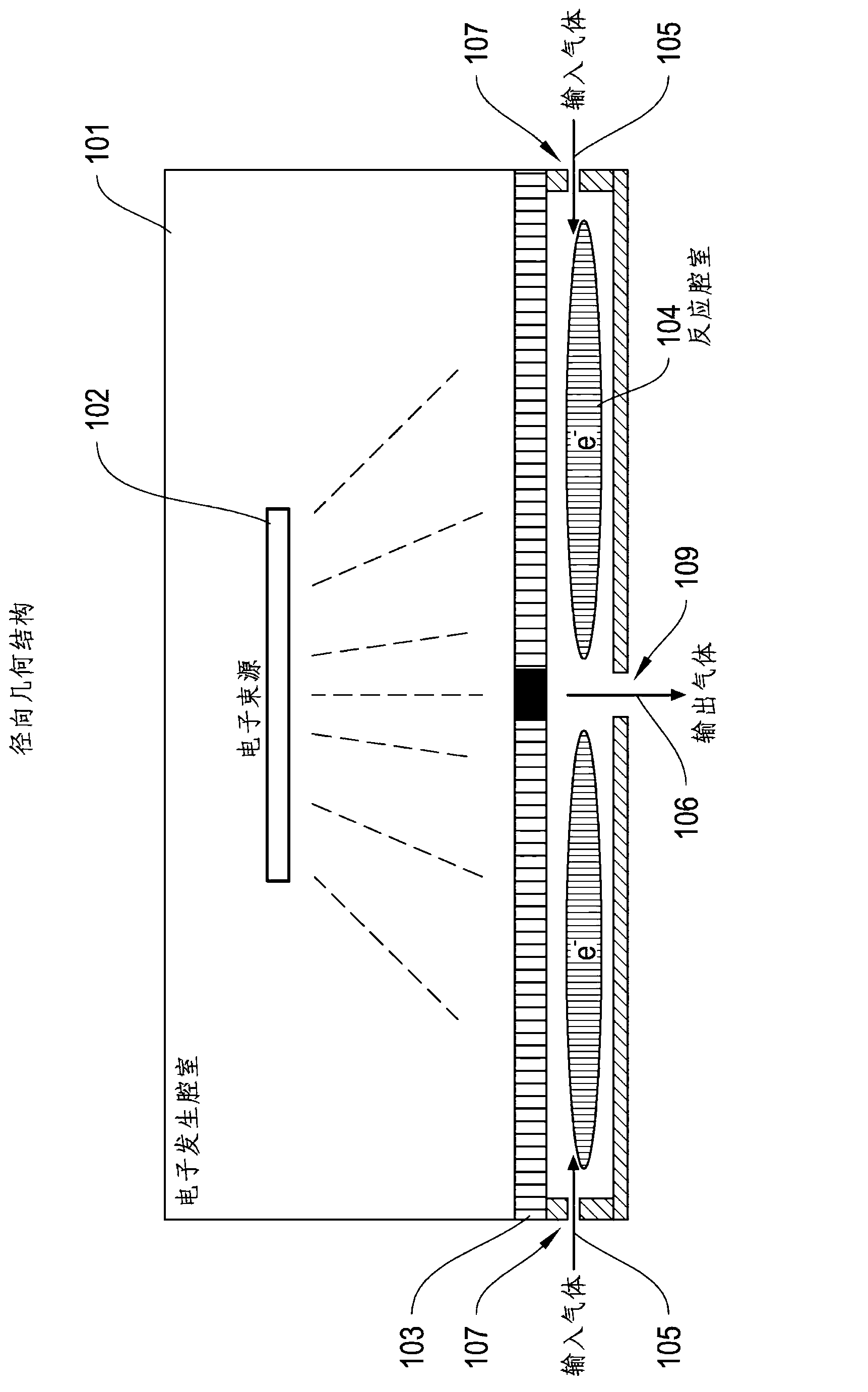
[0026] figure 1 One embodiment of an apparatus 100 for generating ozone or plasma using a radial geometry is illustr...


PUM


Abstract

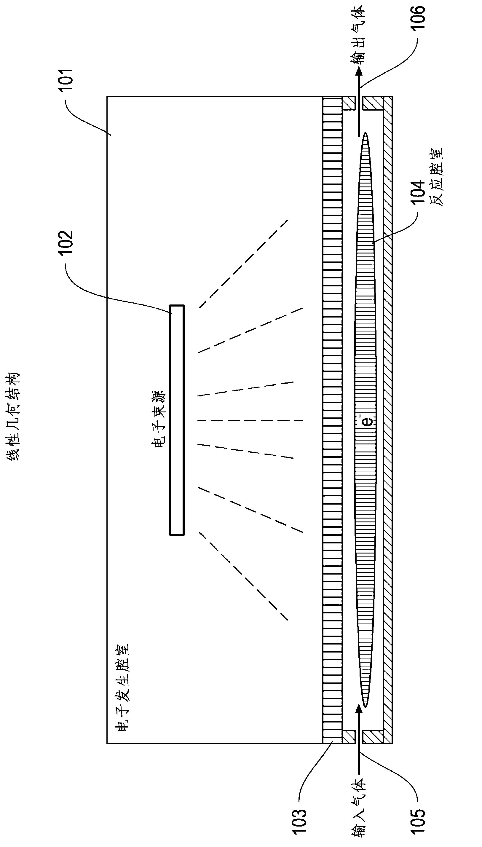
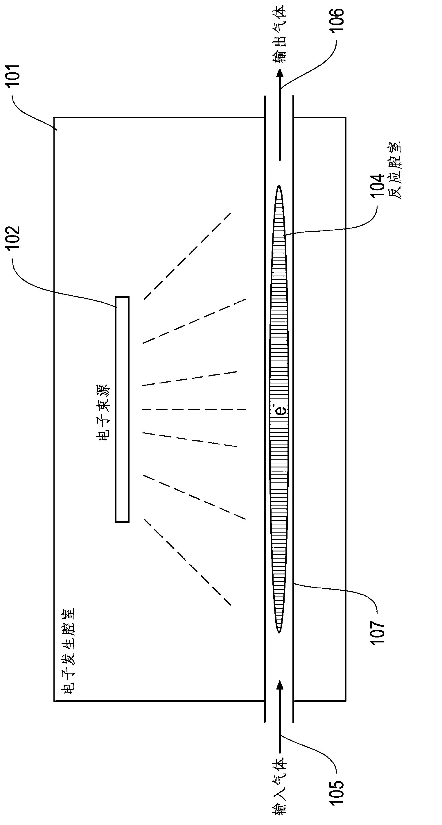
This invention proposes, among other things, systems and methods for providing ozone generators or plasma generators that generate an electric field in an electron generation chamber that is separate from a reaction chamber. An electron beam emitter in an electron generation chamber is configured to emit a beam of electrons and is separated from the reaction chamber by an electron permeable barrier that provides a window through which the beam of electrons passes. The electrons are accelerated to the required energy in the electron generation chamber and transmitted through the barrier to the reaction chamber, where an input gas source introduces an input gas into the reaction chamber. The input gas may react with the beam of electrons inside the reaction chamber to form an output gas comprising a plasma or a concentration of ozone, and the output gas passes from the reaction chamber to a wafer processing chamber.

Description

[0001] Cross References to Related Applications [0002] This application claims U.S. Provisional Patent Application 61 / , filed December 16, 2010, entitled "Ozone and Plasma Generation Using Electron Beam Technology" under 35 U.S.C. § 119, U.S. Code 423,693, which is incorporated herein in its entirety. technical field [0003] In general terms, the present invention relates to systems and methods for generating ozone and plasma using electron beam technology. Background technique [0004] Ozone and plasma generation technologies rely on the principle of supplying energy to an input gas to form charge carriers (electrons and ions) and additional plasma species. The most common method used in industrial applications to generate and maintain ozone and plasma is by applying an electric field to the input gas. There are currently several methods for generating and applying electric fields for these applications. Typically, the ozone and plasma generation techniques are config...

Claims


Application Information

Patent Timeline
Patent Type & Authority Applications(China)
IPC IPC(8): H01L21/306
CPCC01B13/10H01J3/02H01J33/00H01J37/3233H01J37/32357H01J37/32816B01J19/085
Inventor 卡维·巴赫塔里
Owner HITACHI ZOSEN CORP
Learn More