
Integrated circuit design and manufacturing method and integrated circuit design system

A technology of integrated circuits and manufacturing methods, applied in CAD circuit design, design optimization/simulation, computer-aided design, etc., can solve problems such as inability to effectively provide optimized wafers

Active Publication Date: 2020-10-23
TAIWAN SEMICON MFG CO LTD
View PDF11 Cites 0 Cited by
  • Summary
  • Abstract
  • Description
  • Claims
  • Application Information

AI Technical Summary

Problems solved by technology

Current methods cannot effectively provide optimized wafers under the constraints of circuit performance and manufacturing cost

Method used


Image

  • Integrated circuit design and manufacturing method and integrated circuit design system
  • Integrated circuit design and manufacturing method and integrated circuit design system
  • Integrated circuit design and manufacturing method and integrated circuit design system

Examples


Embodiment Construction

[0050] The following disclosure provides many different embodiments or examples for implementing different features of the present invention. The following disclosure describes specific examples of various components and their arrangements to simplify the description. Of course, these specific examples are not intended to be limiting. For example, if the present invention describes that a first feature is formed on or above a second feature, it means that it may include an embodiment in which the above-mentioned first feature is in direct contact with the above-mentioned second feature, and may also include additional features. Embodiments in which a feature is formed between the first feature and the second feature such that the first feature and the second feature may not be in direct contact. In addition, the same reference signs and / or symbols may be reused in different examples in the following publications. These repetitions are for simplicity and clarity and are not i...


PUM


Abstract

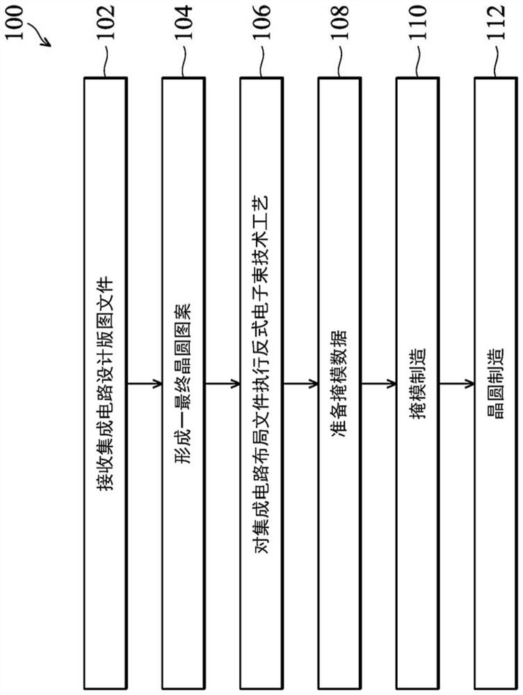
The invention provides an integrated circuit design and manufacture method and an integrated circuit design system. The integrated circuit design and manufacturing method includes: receiving an integrated circuit layout file; and performing a reverse electron beam technology process on the integrated circuit layout file to generate a final mask pattern, wherein the reverse electron beam technology process uses a single reverse electron Beam technology models to simulate a mask process as well as wafer process.

Description

technical field [0001] The invention relates to a method for producing a mask, in particular to a method for producing a mask for a semiconductor wafer. Background technique [0002] With the continuous advancement of semiconductor technology for size reduction (for example, 32nm, 28nm and below 20nm process), integrated circuit design is becoming more and more difficult. The performance of a designed circuit is heavily affected by the image of various circuit patterns, such as doped wells, sources and drains, gates, vias / contact pads, and other circuit features. As advanced circuit designs have three-dimensional architectures that include fin-like active regions, it further complicates the difficulty of forming circuits with proper shape and size requirements. In order to enhance the imaging effect in the process of converting the designed pattern into the wafer, optical proximity correction (optical proximity correction, OPC) is indispensable. The designed pattern is adj...

Claims


Application Information

Patent Timeline
Patent Type & Authority Patents(China)
IPC IPC(8): G06F30/392
CPCG06F30/30G03F1/36G03F7/70433G03F7/70441G03F7/705G06F30/398G06F30/20G06F30/392G06F2119/18
Inventor 黄旭霆刘如淦周硕彦高蔡胜
Owner TAIWAN SEMICON MFG CO LTD
Learn More