Roadbed slop vertical vibrating compacting device

A vertical vibrating and compacting device technology, which is applied in the direction of roads, roads, road repairs, etc., to achieve the effects of high work reliability, easy promotion and use, and low cost

Active Publication Date: 2013-08-28
SHAANXI JOINTARK MASCH GRP CO LTD
View PDF7 Cites 17 Cited by
  • Summary
  • Abstract
  • Description
  • Claims
  • Application Information

AI Technical Summary

Problems solved by technology

The subgrade slope vertical vibration compaction device can effectively vibrate and compact the subgrade slope, and

Method used


Image

  • Roadbed slop vertical vibrating compacting device
  • Roadbed slop vertical vibrating compacting device
  • Roadbed slop vertical vibrating compacting device

Examples


Example Embodiment

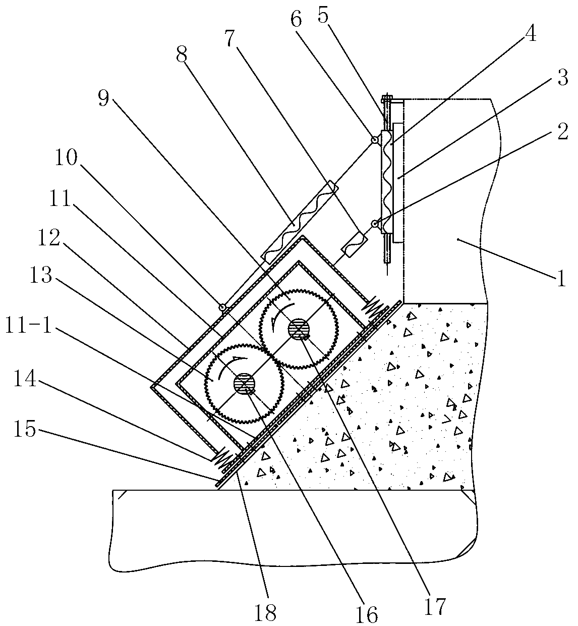
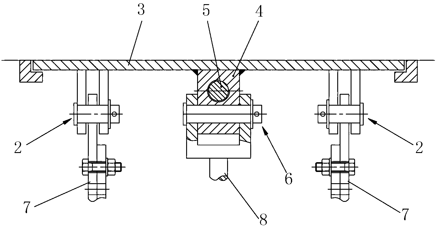
[0041] like Figure 1-Figure 6 The shown vertical vibration compacting device for roadbed slope includes a vertical vibration mechanism obliquely connected to the side wall of the working device 1, the vertical vibration mechanism includes a vibration box 11, and the vibration box 11 is rotatably connected with A rotating shaft one 17 and a rotating shaft two 16 parallel to each other, a synchronizing gear one 9 is installed on the rotating shaft one 17, and a synchronizing gear two 13 meshing with the synchronizing gear one 9 is installed on the described rotating shaft two 16, so The first eccentric block 23 is installed on the first rotating shaft 17, the second eccentric block 22 is installed on the second rotating shaft 16, and the bottom plate 11-1 of the vibration box 11 is connected with A tamping plate 15, on which a driving device 19 for driving the first rotating shaft 17 or the second rotating shaft 16 to rotate is installed.

[0042] In this embodiment, the worki...


PUM


Abstract

The invention discloses a roadbed slop vertical vibrating compacting device which comprises a vertical vibrating mechanism aslant connected to the side wall of a working device, wherein the vertical vibrating mechanism comprises a vibrating box body, a rotating shaft I and a rotating shaft II which are mutually parallel are rotatably connected into the vibrating box body, a synchronizing wheel I is arranged on the rotating shaft I, a synchronizing gear II meshed with the synchronizing gear I is arranged on the rotating shaft II, an eccentric block I is arranged on the rotating shaft I, an eccentric block II is arranged on the rotating shaft II, a tamping plate supporting against a roadbed slope is connected to a bottom plate of the vibrating box body, and a drive device used for driving the rotating shaft I or rotating shaft II to rotate is arranged on the tamping plate. The roadbed slop vertical vibrating compacting device is capable of carrying out effective vibrating compaction on the roadbed slope, and is good in use effect, easy to operate and convenient to popularize and use.

Description

technical field [0001] The invention relates to a vibration compacting device, in particular to a vertical vibration compacting device for a roadbed slope. Background technique [0002] The edge slope of the material layer (referred to as the subgrade slope) formed by the paver during the paving operation of the water-stabilized layer is generally formed by the free rolling of the material. Its organizational structure is loose and its stability is extremely poor. It is easy to collapse when pressing this kind of edge, especially when the material layer is thicker, the collapse may cause a rollover accident, so in many cases, the road roller cannot complete the rolling of this kind of edge, which will make the edge of the road surface less compacted and affect the bearing capacity of the road surface capacity and cause early damage, shortening the service life of the pavement. In order to improve the edge compaction of the material layer, sometimes the supporting edge formw...

Claims


Application Information

Patent Timeline
IPC IPC(8): E01C19/38
Inventor 綦开隆武鸿
Owner SHAANXI JOINTARK MASCH GRP CO LTD
Why Eureka
Try Eureka