
Ultra-low pressure flare gas burning device

A combustion device and torch gas technology, applied in the direction of gas fuel burners, burners, combustion methods, etc., can solve the problems of environmental pollution, low-pressure torch gas cannot be fully burned, etc., and achieve high combustion efficiency, low pressure, and full combustion Effect

Active Publication Date: 2013-08-28
JIANGSU SUNPOWER TECH
View PDF6 Cites 2 Cited by
  • Summary
  • Abstract
  • Description
  • Claims
  • Application Information

AI Technical Summary

Problems solved by technology

[0003] The purpose of the present invention is to design a device that can satisfy both high-pressure flare gas combustion and low-pressure or ultra-low pressure flare gas combustion in view of the problem that the existing flare gas combustion device cannot fully burn low-pressure flare gas and easily causes environmental pollution. An ultra-low pressure flare gas combustion device

Method used


Image

  • Ultra-low pressure flare gas burning device
  • Ultra-low pressure flare gas burning device

Examples


Embodiment Construction

[0016] The present invention will be further described below in conjunction with the accompanying drawings and embodiments.

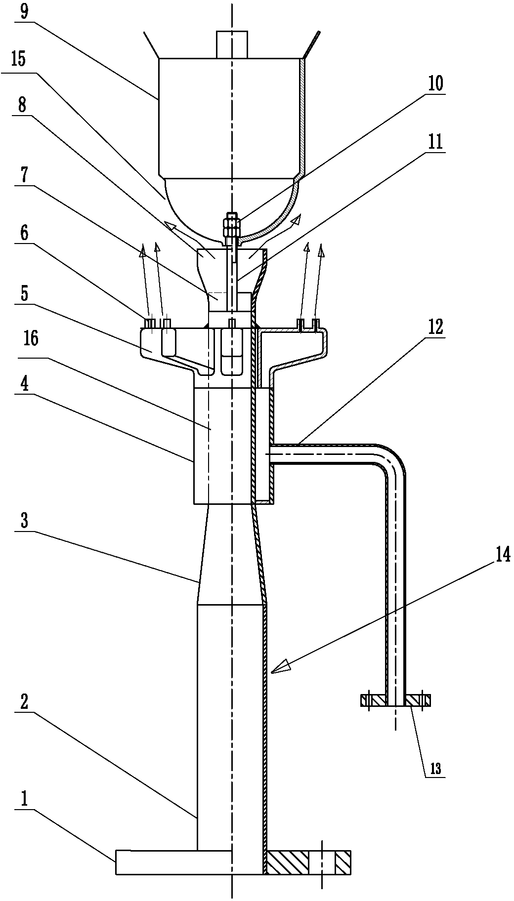
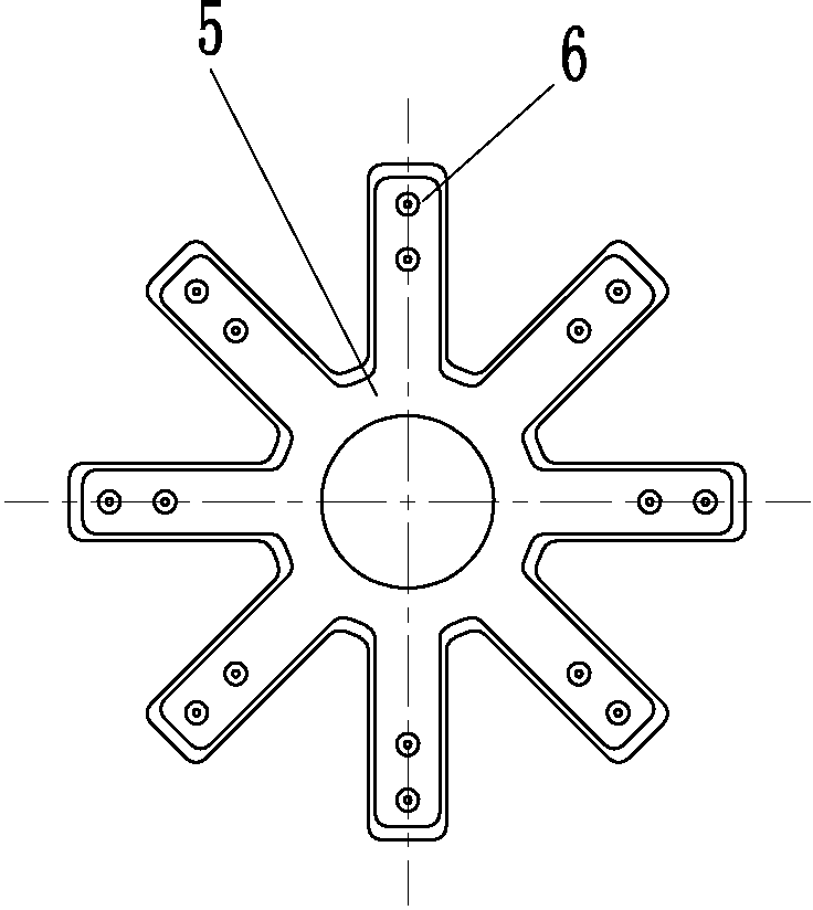
[0017] Such as Figure 1-2 shown.

[0018] An ultra-low pressure flare gas combustion device, which includes a drum 9, a burner 8 and a flare gas inlet pipe 14, the flare gas inlet pipe 14 can be composed of a connecting pipe 2, a scaling pipe 3 and a straight pipe 16, and the lower end of the connecting pipe 2 passes through The large flange 1 communicates with the air supply pipeline, the upper end of the connecting pipe 2 communicates with the large end of the zoom tube 3, the upper end of the zoom tube 3 communicates with the lower end of the straight tube 16, and the burner 8 communicates with the upper end of the straight tube 16. Ribs 7 are installed in the burner 8, and the bottom 15 of the drum 9 is positioned on the top of the burner 8 through the connecting bolts 11 connected to the ribs 7; the flare gas at the bottom of the burner 8 Co...


PUM


Abstract

An ultra-low pressure flare gas burning device comprises a boiler cylinder (9), a burner (8) and a flare gas inlet pipe (14). The burner (8) is connected with one end of the flare gas inlet pipe (14). The ultra-low pressure flare gas burning device is characterized in that a rib plate (7) is arranged in the burner (8), a boiler bottom (15) of the boiler cylinder (9) is located on the upper portion of the burner (8) through a connecting bolt (11) connected with the rib plate (7) and a nut (10). A cone body (5) is sleeved on the flare gas inlet pipe (14) on the lower portion of the burner (8). A nozzle (6) communicated with an inner cavity of the cone body (5) is arranged on the upper end closed end face of the cone body (5). The lower end of the cone body (5) is communicated with one end of a casing pipe (4) which is sleeved on the flare gas inlet pipe (14) as well. The lower end of the casing pipe (4) is in a closed state. The casing pipe (4) is connected with a branch pipe (12) used for supplying steam or air or gas. According to the ultra-low pressure flare gas burning device, pressure required for combustion is low, auxiliary steam using amount is small, and meanwhile full combustion of the flare gas can be guaranteed. The ultra-low pressure flare gas burning device is particularly suitable for disposal with the ultra-low pressure flare gas.

Description

technical field [0001] The invention relates to an environmental protection purification equipment for petrochemical, metallurgy, light industry, oil refining and other industries, in particular to a flare gas discharge combustion device, specifically an ultra-low pressure flare gas combustion device. Background technique [0002] At present, when the general-purpose ground flare burner handles low-pressure or ultra-low pressure flare gas, due to the extremely low velocity of the gas at the burner outlet and the insufficient amount of low-injected air, it will cause incomplete combustion, black smoke, and low flame rigidity. Especially when burning low-pressure flare gas containing heavy components, it will cause carbon deposits in the burner, which poses a great safety hazard. Even under the smoke elimination effect of the auxiliary smoke elimination steam, although a little pollutant can be reduced, it is far from achieving the purpose of complete smoke elimination. At...

Claims


Application Information

Patent Timeline
Patent Type & Authority Applications(China)
IPC IPC(8): F23D14/22F23D14/58
Inventor 郭宏新何松李奇刘丰马明赵志红李逸峰余晓燕
Owner JIANGSU SUNPOWER TECH
Learn More