Method for measuring upper terminal difference and lower terminal difference of horizontal-type three-section feed water heater

A water heater and heater technology, applied in the direction of instruments, measuring devices, etc., can solve the problems of wrong and missing measurement data, and high measurement cost of data acquisition system

Active Publication Date: 2013-08-28
DATANG NANJING POWER PLANT +1
View PDF3 Cites 7 Cited by
  • Summary
  • Abstract
  • Description
  • Claims
  • Application Information

AI Technical Summary

Problems solved by technology

[0004] In the actual operation of the unit, although there are water outlet and drain temperature measurement points of the heater, its variable working condition characteristics can be obtained, but due to poor operating conditions, weak maintenance and other reasons, the measurement reliability and economic efficiency are generally poor. Problems: Resistive sensors are often used in thermal measurement systems, and the corresponding data acquisition system has a high measurement cost; when the working conditions change greatly, the water temperature response shows a large thermal inertia, which affects the measurement accuracy; the site installation location is complicated , once the sensor fails, the measurement data will be wrong or missing, so a method suitable for quickly measuring the end difference in the field is needed
[0005] In the traditional calculation method of heater end difference, some of them assume that the heat transfer coefficien...

Method used


Image

  • Method for measuring upper terminal difference and lower terminal difference of horizontal-type three-section feed water heater
  • Method for measuring upper terminal difference and lower terminal difference of horizontal-type three-section feed water heater
  • Method for measuring upper terminal difference and lower terminal difference of horizontal-type three-section feed water heater

Examples


Embodiment

[0044] Embodiment: In this embodiment, the method for calculating the upper end difference and the lower end difference of the high-pressure heater of a 330MW steam turbine unit #1 of Harbin Steam Turbine includes the following steps:

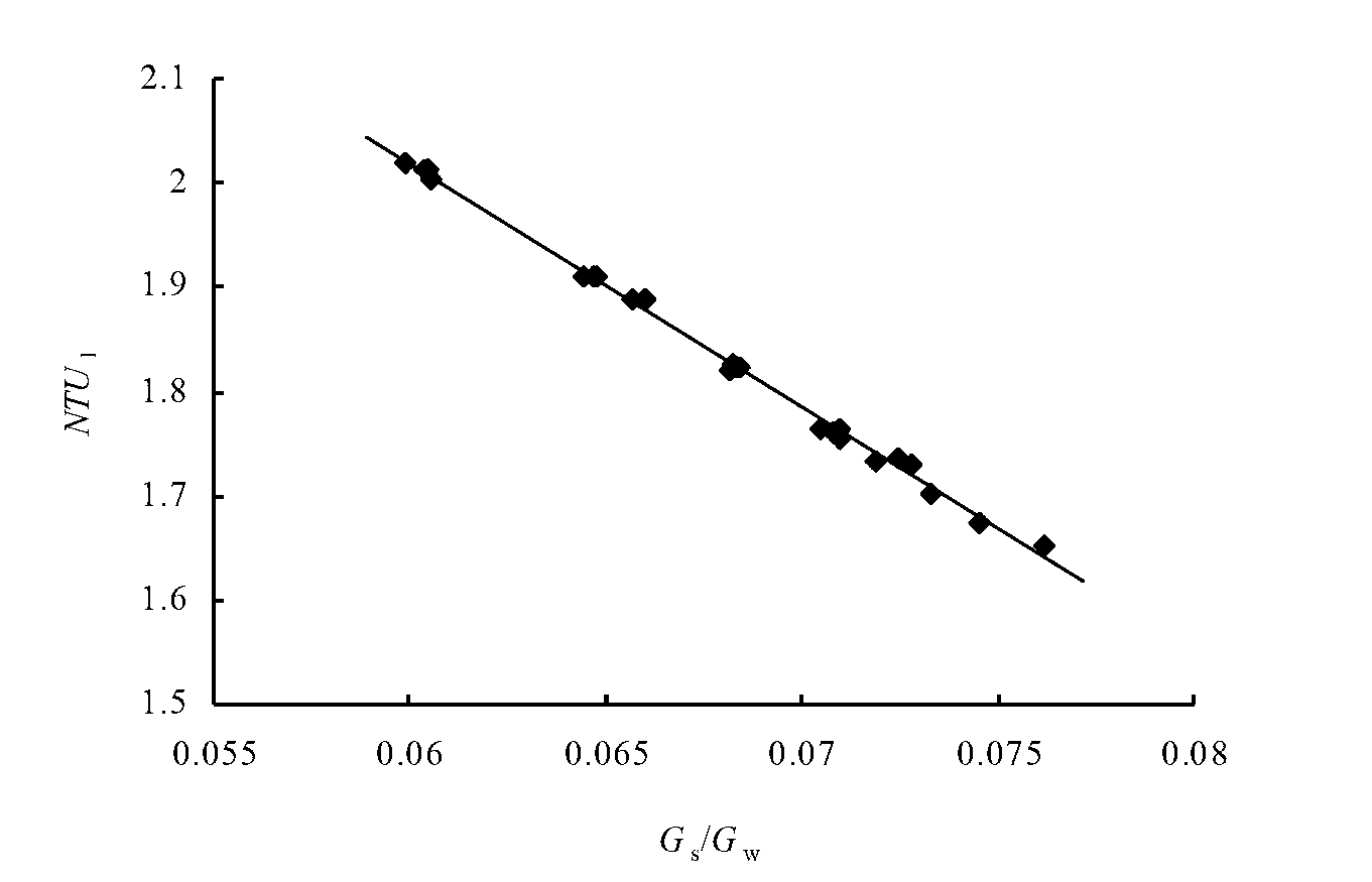
[0045] (1) Calculate the number of heat transfer units NTU in the drain cooling section of the heater 1 and extraction steam flow G s , Feedwater flow G w The ratio of G s / G w The linear relationship:

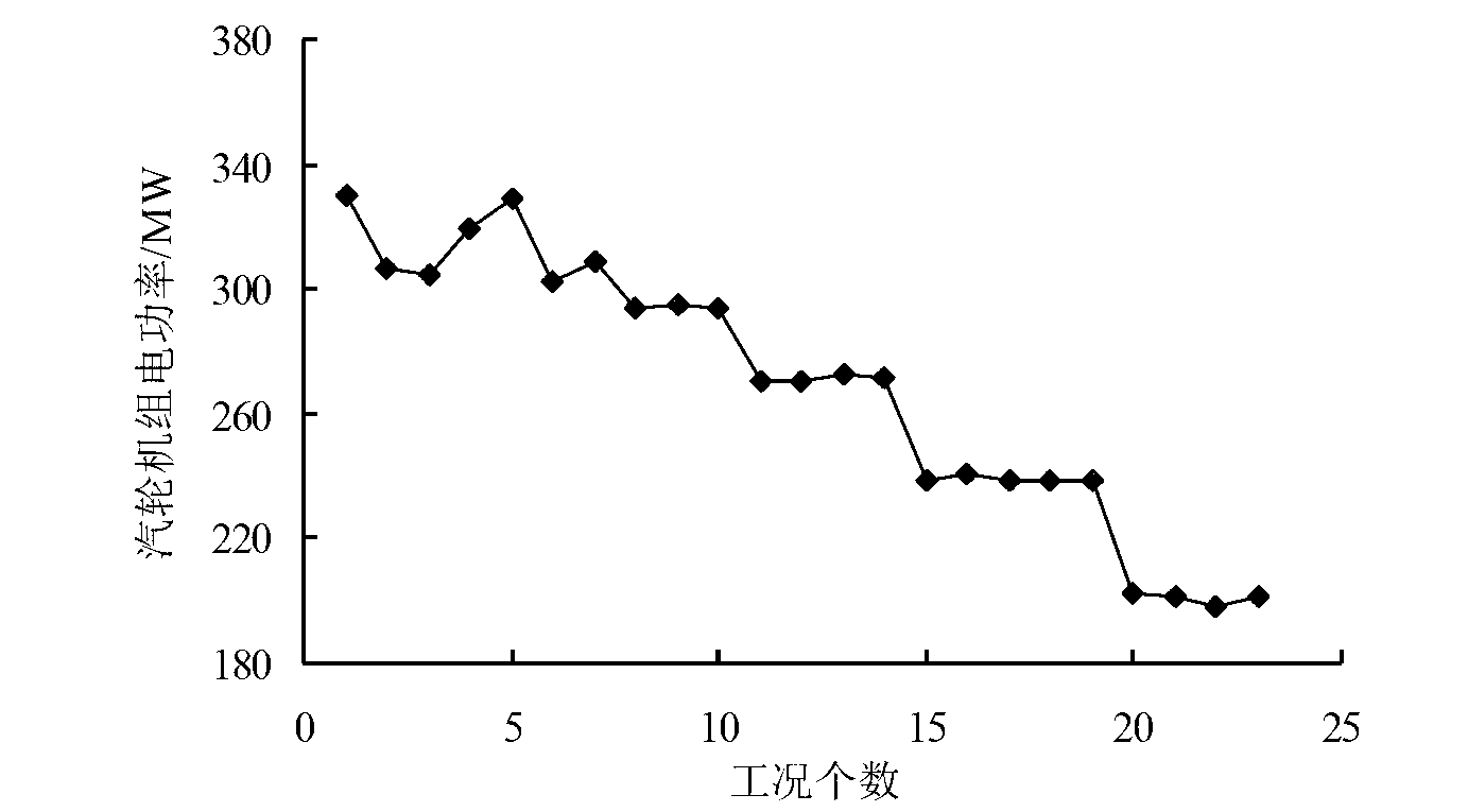
[0046] (11) Set 23 test conditions with different powers, and the 23 test conditions correspond to the changes in the electric power of the steam turbine generator set as follows: figure 1 As shown, under each test condition, the heater feed water pressure p is obtained by measuring the temperature and pressure measuring instrument w , saturation pressure p h , Hydrophobic temperature t od and feedwater inlet temperature t w1 , using the flow measuring instrument to measure the extraction steam flow G of the heater s and feedwater flow...


PUM


Abstract

The invention discloses a method for measuring upper terminal difference and lower terminal difference of a horizontal-type three-section feed water heater. Data fitting is conducted on a dewatering cooling section, a condensation section and a superheated steam cooling section to obtain simplified linear function relations between the number of heat-transfer units of all the sections and a certain parameter, and the upper terminal difference and the lower terminal difference are calculated according to the simplified linear function relations. According to the method, analysis can be respectively conducted on the dewatering cooling section, the condensation section and the superheated steam cooling section of the heater on the basis of the dimension analysis principle and operation measurable parameters. By means of the simplified linear function relations between the number of the heat-transfer units of all the sections of the horizontal-type three-section feed water heater and the certain parameter, all thermal parameters of an inlet and an outlet of the water heater in any given operation condition can be finally obtained, and the upper terminal difference and the lower terminal difference can be obtained. The method provides reference for guaranteeing variable operation condition performance of the water heater, and is simple, rapid, wide in application range, and high in accuracy.

Description

technical field [0001] The invention relates to a horizontal three-stage feed water heater, in particular to a method for measuring and calculating the upper end difference and the lower end difference of the horizontal three-stage feed water heater. Background technique [0002] Modern large-scale thermal power plants all use heat recovery systems to reduce cold source losses and improve unit cycle thermal efficiency, which can generally increase thermal economy by 10% to 20%. Among them, the feed water heater is the core of the heat recovery system, and its operating performance has a great impact on the entire unit. The site usually uses the size of the end difference to evaluate the operating characteristics of the heater. [0003] At present, most high-pressure heaters of large-scale thermal power units use horizontal three-stage U-shaped tube heaters. The feed water enters the water chamber from the feed water inlet pipe, enters the heat transfer section through the lo...

Claims


Application Information

Patent Timeline
IPC IPC(8): G01D21/00
Inventor 胥建群杨涛石永锋周克毅
Owner DATANG NANJING POWER PLANT
Why Eureka
Try Eureka