Esd protection device and method for producing same
A technology of ESD protection and manufacturing method, applied in the direction of static electricity, electrical components, spark gaps, etc., can solve problems such as holes formed in insulating substrates, achieve the effect of improving repeatability and suppressing the rise of discharge start voltage
- Summary
- Abstract
- Description
- Claims
- Application Information
AI Technical Summary
Problems solved by technology
Method used
Image

Examples
Embodiment 1)
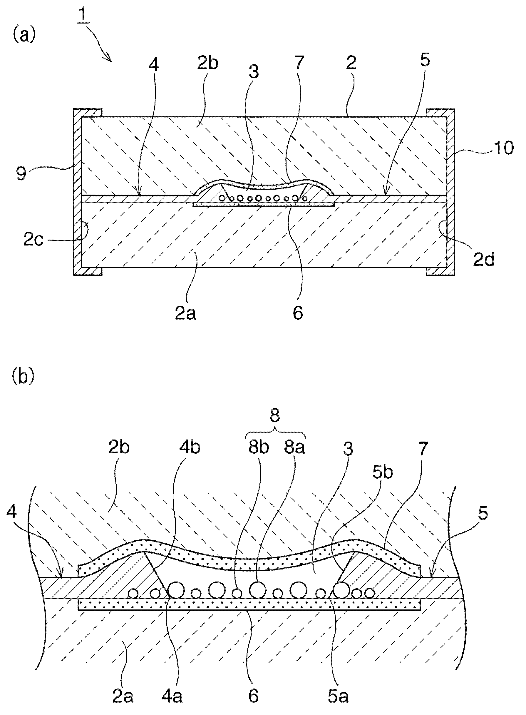
[0076] A Ba-Al-Si-O ceramic composition is prepared and pre-fired at 700-900°C. The obtained calcined powder is pulverized to obtain raw material ceramic powder. A mixed solvent of toluene and alcohol (Japanese: エキネン) was added and mixed to this raw ceramic powder to obtain a ceramic slurry in which a resin binder and a plasticizer were further added. The ceramic slurry thus obtained was formed by a doctor blade method to obtain a ceramic green sheet having a thickness of 50 μm. As described above, a plurality of ceramic green sheets having a thickness of 50 μm were prepared.
[0077] In addition, a ceramic paste for forming the sealing layer 6 was printed to a thickness of 10 μm on one ceramic green sheet, and dried. As the ceramic paste used, a ceramic paste containing Al2O3 was used.
[0078] After drying the above-mentioned ceramic paste, the composite paste for forming the discharge assisting portion 8 is applied and dried. This composite paste is prepared by weighing...
Embodiment 2)
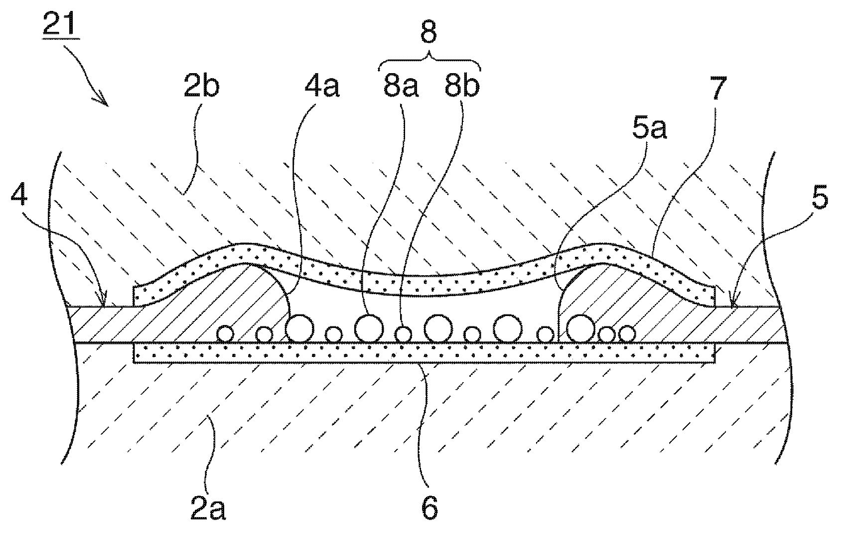
[0086] The ESD protection device 21 in Embodiment Mode 2 was produced. When forming the 1st, 2nd discharge electrode 4,5, similarly to Example 1, the conductive paste was printed multiple times. However, by changing the printing accuracy of the printed pattern, the first and second discharge electrodes 4 and 5 whose tip thicknesses are circular are formed.
[0087] The size of the gap between the tips of the first and second discharge electrodes 4 and 5 was 30 μm. In addition, the thickness of the thickest part of the first and second discharge electrodes 4 and 5 is 30 μm. The dimension of the lowest part of the cavity 3 is 10 μm.
Embodiment 3)
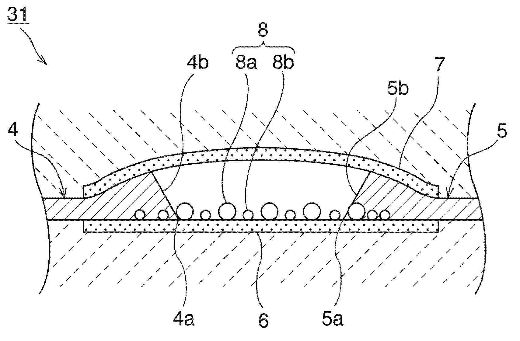
[0089] formed as image 3 The ESD protection device 31 in Embodiment 3 is shown. Here, it is the same as in Example 1 except that the coating thickness of the resin paste for forming the cavity 3 is 20 μm. As a result, as image 3 As shown, it is possible to form a dome-shaped cavity 3 whose top protrudes upward at the center. The distance of the gap between the first and second discharge electrodes was 30 μm. The thickness of the thickest portion of the first and second discharge electrodes was 30 μm. The height of the highest portion at the top at the center of the cavity 3 was 35 μm.
PUM
 Abstract
Description
Claims
Application Information
 - R&D
- Intellectual Property
- Life Sciences
- Materials
- Tech Scout
- Unparalleled Data Quality
- Higher Quality Content
- 60% Fewer Hallucinations
Browse by: Latest US Patents, China's latest patents, Technical Efficacy Thesaurus, Application Domain, Technology Topic, Popular Technical Reports.
© 2025 PatSnap. All rights reserved.Legal|Privacy policy|Modern Slavery Act Transparency Statement|Sitemap|About US| Contact US: help@patsnap.com