Special air saving unit for pneumatic conveying and control system of special air saving unit

A control system and material conveying technology, which is applied in the direction of conveying bulk materials, conveyors, transportation and packaging, etc., can solve the problems of low downstream pressure, waste, and increased conveying flow

Inactive Publication Date: 2013-09-04
北京爱索能源科技股份有限公司
View PDF6 Cites 7 Cited by
  • Summary
  • Abstract
  • Description
  • Claims
  • Application Information

AI Technical Summary

Problems solved by technology

[0004] (1) The downstream pressure will fluctuate greatly due to the change of the material state in the pipeline. When the downstream pressure increases, the delivery flow will decrease, and the accumulation of material in the pipeline will cause blockage
[0005] (2) The downstream pressure is low, and the delivery flow increases to generate waste

Method used


Image

  • Special air saving unit for pneumatic conveying and control system of special air saving unit

Examples


Embodiment Construction

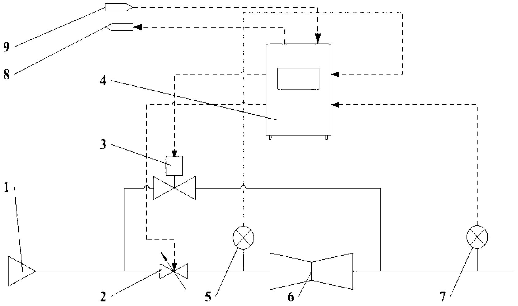
[0014] 1. The control unit has a touch screen, communicates with the main control PLC, displays the real-time curve of upstream and downstream pressure and valve opening feedback, and can set the opening and closing of each valve and program control parameters by touching the buttons.

[0015] 2. The control program is divided into manual state and automatic state. In the manual state, the valve action is manually operated through the touch screen. The opening of the main regulating valve (2) can be set and the opening value can be fed back; if the bypass valve (3) is an on-off valve, its switching value can be set and the on-off status can be fed back; if the bypass valve (3) is a regulating valve, Its opening can be set and the opening value can be fed back. When the material is conveyed, through the debugging of the valve in the manual state, you can know the upstream pressure range of the steady flow element (6) and the corresponding opening range of the regulating valve (...


PUM


Abstract

The invention relates to a special air saving unit for pneumatic conveying and a control system of the special air saving unit, and belongs to the field of energy conservation of pneumatic systems. The special air saving unit is mainly used for controlling flow and pressure of a system for pneumatically conveying materials by the aid of compressed air, the flow and upstream pressure are kept in proportional relation by a flow stabilizing element (6) when downstream pressure fluctuates within a certain range, stability of the upstream pressure is controlled by an adjusting valve (2) at the upstream of the flow stabilizing element (6), gas flow is kept at a needed constant value, and purge flow peak and flow reduction due to blockage are effectively avoided. According to operating parameters of an air compressor, peak load shaving functions can be achieved for air consumption, system pressure is stabilized, and operating electric energy of the air compressor can be saved.

Description

technical field [0001] The invention belongs to the field of energy saving of pneumatic systems, and relates to system flow and pressure control for pneumatic conveying of materials by using compressed air. Background technique [0002] The pneumatic conveying system uses compressed air to convey powdery and granular materials. The principle is to mix the compressed air with the material, and use the compressed air pressure to convert the kinetic energy of the air and material mixture, so that the material is transported in the pipeline. However, due to factors such as pipeline diameter, unreasonable design of air supply pressure, and lack of flow control means, the air flow rate of the pneumatic conveying system often produces a lot of waste, which affects the pressure of the compressed air system and results in energy consumption of the air compressor. increase. Therefore, the necessary transformation of the air supply pipeline for pneumatic conveying and reasonable contr...

Claims


Application Information

Patent Timeline
Patent Type & Authority Applications(China)
IPC IPC(8): B65G53/66
Inventor 许启跃李晶
Owner 北京爱索能源科技股份有限公司
Why Eureka
Try Eureka