Removing type anchorage device

An anchoring and removal technology, which is used in the installation of anchor rods, sheet pile walls, mining equipment, etc., can solve the problem of inability to remove tension members for disassembly, increased difficulty in processing and assembly, and cumbersome removal of tension members. problems, to achieve excellent technical difficulty, unique technical difficulty, and improve the effect of mechanical reliability

Active Publication Date: 2013-09-04
杭州富阳吉良建材有限公司
View PDF5 Cites 4 Cited by
  • Summary
  • Abstract
  • Description
  • Claims
  • Application Information

AI Technical Summary

Problems solved by technology

[0007] The present invention aims at the problems of increased production, processing and assembly difficulty and reduced economic efficiency caused by the complicated anchor structure in the prior art, and if the dismantling tension member is removed before the dismantling occurs due to operational errors and other reasons When the tension member is loose, slippage may be caused by being pulled, and the receding central material cannot be retreated, and the tension member for disassembly cannot be removed; the process of removing the tension member is too cumbersome, providing a simple structure , can improve the convenience of production, assembly and use, and ensure mechanical reliability and ease of disassembly operations.

Method used


Image

  • Removing type anchorage device
  • Removing type anchorage device
  • Removing type anchorage device

Examples


Embodiment 1

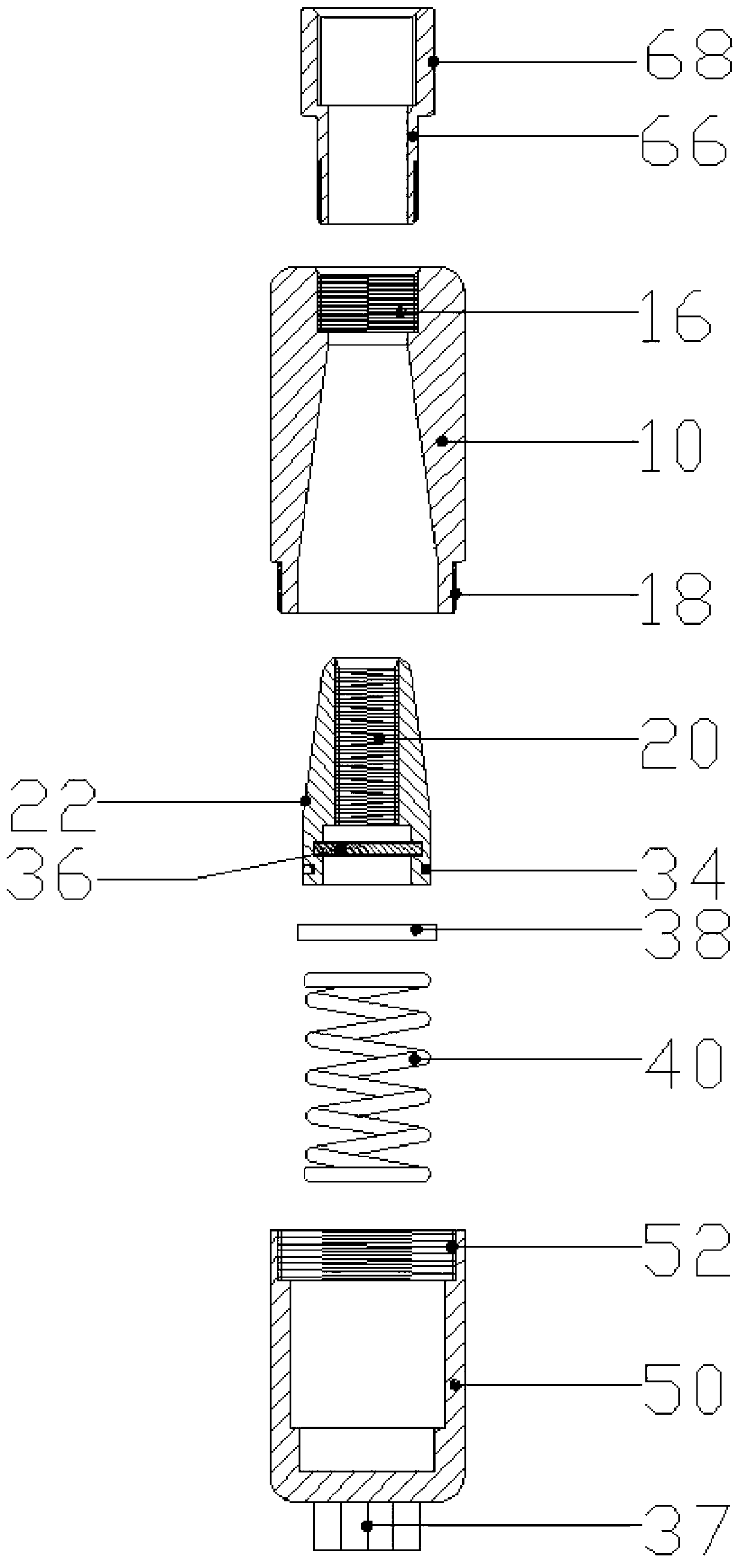
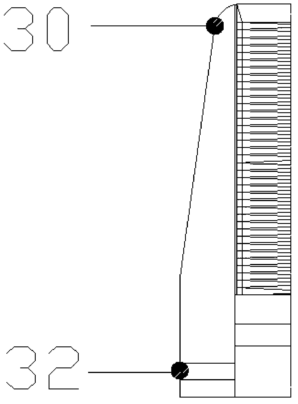
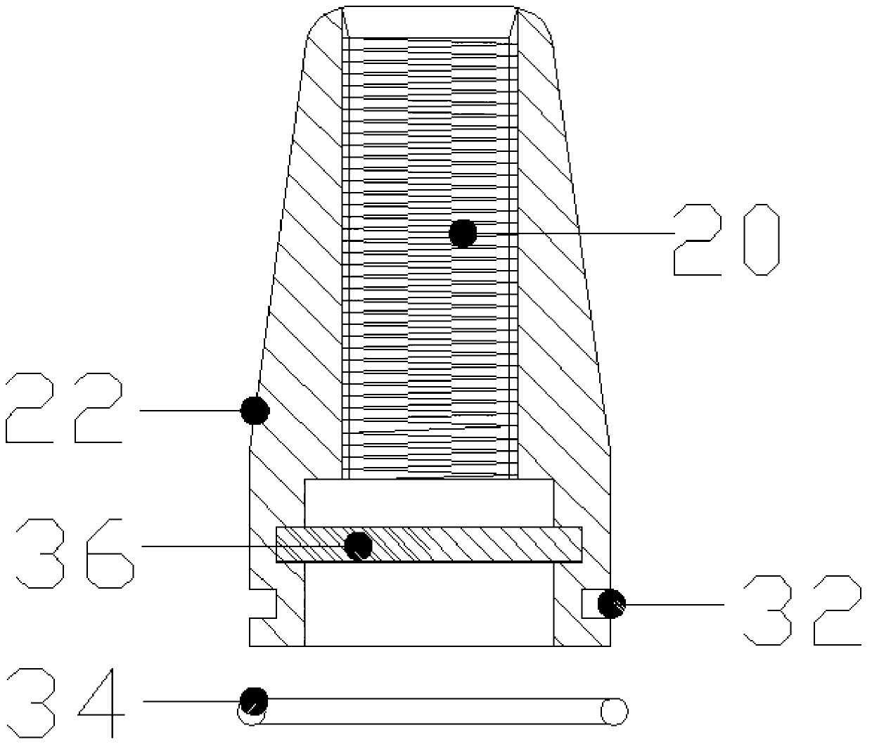
[0030] Removable anchors, such as Figure 1 to Figure 7 As shown, it includes a waterproof cover 10, an anchor ring extrusion sleeve 22, a spring 40 and a headgear 50, and also includes a leaf spring 38. The inside of the waterproof cover 10 is a tapered groove with a narrow top and a wide bottom. The anchor ring extrusion sleeve 22 is composed of three Made up of two clips 30 of the same shape, the shape of the anchor ring extrusion sleeve 22 is tapered with a narrow top and a wide bottom. Fixed ring 34, leaf spring 38 are placed between anchor ring extrusion sleeve 22 and spring 40, leaf spring 38 outer diameter is identical with anchor ring extrusion sleeve 22 lower end outer diameters, and headgear 50 is the closed cylinder body of top open bottom. The anchor ring extrusion sleeve 22 can move in the tapered groove, and the leaf spring 38 is used to support the anchor ring extrusion sleeve 22 and prevent the three clips 30 from moving up and down relative to each other.

...


PUM


Abstract

The invention relates to an anchorage device used in buildings and civil construction, and discloses a removing type anchorage device. The removing type anchorage device comprises a water-proof cover, an anchor ring extrusion sleeve, a spring and a head sleeve, and further comprises a plate spring. A cone-shaped ditch with the narrow upper portion and the wide lower portion is formed inside the water-proof cover. The anchor ring extrusion sleeve is composed of three clamping pieces of the same shape. The anchor ring extrusion sleeve is of a cone shape with the narrow upper portion and the wide lower portion. An annular concave groove is formed in the periphery of the lower end of the anchor ring extrusion sleeve. An anchor ring fixing ring is arranged in the annular concave groove. The plate spring is arranged between the anchor ring extrusion sleeve and the spring. The external diameter of the plate spring is the same with the external diameter of the lower end of the anchor ring extrusion sleeve. The head sleeve is a cylinder with the open upper portion and the closed lower portion. The removing type anchorage device is very simple in overall structure in the machining and manufacturing process, high in working efficiency of assembling and disassembling, and capable of reducing manufacturing processes, saving production cost, and achieving the effects of facilitating operation and shortening time.

Description

technical field [0001] The invention relates to an anchor used in building and civil engineering construction, in particular to a removable anchor. Background technique [0002] When constructing the underground structure of large structures such as high-rise buildings and subways, according to the previous technology, H beams should be vertically fixed around the surrounding depth as the anti-slump protection wall or anti-seepage wall while deepening the underground depth. The H beam hinders the construction of equipment and causes problems such as low work efficiency. The underground diaphragm wall construction method needs to clean up the irregular wall surface, which will cause noise and dust. Therefore, recently, anchors are mostly used as diaphragm walls for construction. [0003] That is, in the construction of underground structures of large structures such as high-rise buildings and subways, in the process of erecting anti-slump retaining walls or anti-seepage wall...

Claims


Application Information

Patent Timeline
Patent Type & Authority Applications(China)
IPC IPC(8): E02D5/76E21D21/00
Inventor 金葰洪
Owner 杭州富阳吉良建材有限公司
Why Eureka
Try Eureka