
Method and system for testing reliability of load switch

A technology of load switch and test system, applied in the direction of circuit breaker testing, etc., can solve the problem of load switch reliability is not clearly defined, there is no test equipment load switch reliability test, etc., to save verification time, simple wiring, stability Good results

Active Publication Date: 2013-09-04
STATE GRID CORP OF CHINA +1
View PDF6 Cites 20 Cited by
  • Summary
  • Abstract
  • Description
  • Claims
  • Application Information

AI Technical Summary

Problems solved by technology

However, the reliability of the load switch has not been clearly defined, and there is no complete set of simple and easy test equipment and test methods to test the reliability of the load switch.

Method used


Image

  • Method and system for testing reliability of load switch

Examples


Embodiment 1

[0041] The test method for load switch mechanical reliability test includes the following steps:

[0042] (1) Place the load switch of the batch under test in the temperature and humidity subsystem.

[0043] (2) Connect the lead-out line of the control coil contact of the load switch under test to the drive terminal of the control subsystem; connect the state contact of the load switch under test to the time test terminal of the control subsystem.

[0044] (3) Set the duty cycle, frequency and temperature and humidity of the pulse power supply module to reach predetermined values ​​through the man-machine interface of the control subsystem; for example: the control subsystem controls the duty cycle of the pulse power supply module to 50%, and the frequency is 60s / times (can also be adjusted to other values).

[0045] (4) The control subsystem sends a pulse excitation signal, records the number of actions, opening action time and closing action time, and starts the mechanical...

Embodiment 2

[0053] The test method for the electrical reliability test of the load switch includes the following steps:

[0054] (1) Install the load switch of the tested batch on the real load subsystem.

[0055] (2) Connect the lead-out line of the control coil contact of the load switch under test to the drive terminal of the control subsystem; connect the state contact of the load switch under test to the voltage drop test terminal of the control subsystem.

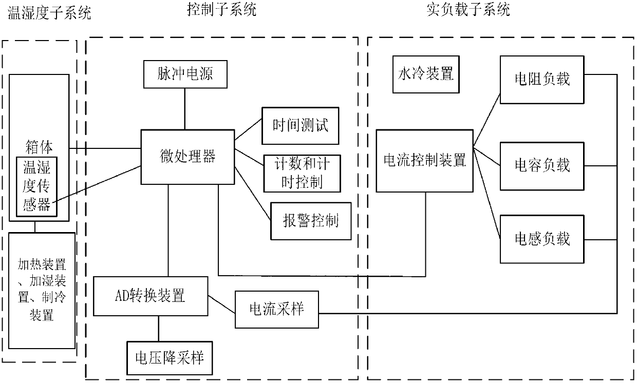
[0056] Adjust the real load subsystem through the control subsystem to make the current value and power factor reach the rated current value and rated power factor of the load switch under test. The power factor is determined by matching the resistive load, inductive load and capacitive load in the real load subsystem. accomplish.

[0057] (3) Set the duty cycle, frequency, current and power factor of the pulse power supply module to reach predetermined values ​​through the man-machine interface of the control subsystem; for exa...


PUM


Abstract

The invention relates to a method and a system for testing the reliability of a load switch, and is characterized in that the method comprises the following steps that (1) a test system is connected with the load switch to be tested; (2) the load switch to be tested and the system are connected; (3) a pulse power module is set; (4) a subsystem sends out a pulse excitation signal; and (5) an alarm ending signal is sent out. The system comprises a control subsystem, an actual load subsystem and a temperature and humidity subsystem. According to the scheme provided by the invention, the reliability of a single-phase load switch and a three-phase load switch can be tested; the time and contact resistance are tested automatically, and stopping conditions are judged automatically; an alarm function is realized and the safety is high; mechanical reliability and electric reliability tests can be carried out automatically without manual operation, and the stability is good; and the wiring is simple and the verification time is saved.

Description

technical field [0001] The invention belongs to the field of power equipment testing, and in particular relates to a method and system for testing the reliability of a load switch. Background technique [0002] The load switch is an important device in the smart energy meter, which plays the role of turning on and off the current loop. When it is applied to the smart energy meter, it also has a special function to cut off the current with a certain load. Its control energy consumption is very low, and it is widely used in smart electric energy meters. It is one of the main components of intelligent electric energy meters. Reliability is tested, including mechanical reliability and electrical reliability. [0003] The load switch is different from other conventional relays. It is a new type of relay and an automatic switch. It needs to be tested for reliability in terms of mechanical properties and electrical properties. The current mechanical industry standard JB / T10923 "M...

Claims


Application Information

Patent Timeline
Patent Type & Authority Applications(China)
IPC IPC(8): G01R31/327
Inventor 张蓬鹤薛阳郜波张起豪黎昊奇鲍文静
Owner STATE GRID CORP OF CHINA
Learn More