Underwater separation electric connector and plug thereof

A technology of electrical connectors and plugs, applied in the parts, connections, electrical components and other directions of connecting devices, can solve the problems of unguaranteed reliability, inconvenient unlocking and separation of plugs and sockets, and failure to solve short-circuit prevention of plugs and sockets.

Active Publication Date: 2013-09-04
CHINA AVIATION OPTICAL-ELECTRICAL TECH CO LTD
View PDF4 Cites 21 Cited by
  • Summary
  • Abstract
  • Description
  • Claims
  • Application Information

AI Technical Summary

Problems solved by technology

When using this method, since the plug and the socket are sealed to each other, in deep water, when the two are separated, it is necessary to overcome the water pressure first, and the water pressure is generally relatively large, for example, at a depth of 100m When separating the electrical connector assembly with a sealed diameter of Φ50, the water pressure to be overcome can reach 2000N, which makes it extremely inconvenient to unlock and separate the plug and socket
In addition, since the socket needs to be soaked in water after being separated from the plug, the reliability of the logic circuit anti-short circuit method cannot be gua

Method used


Image

  • Underwater separation electric connector and plug thereof
  • Underwater separation electric connector and plug thereof
  • Underwater separation electric connector and plug thereof

Examples


Embodiment Construction

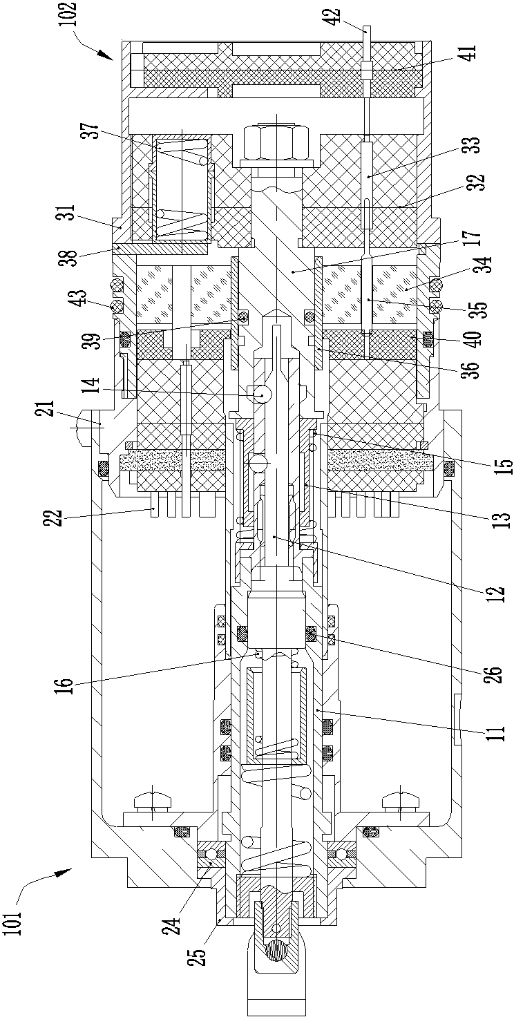
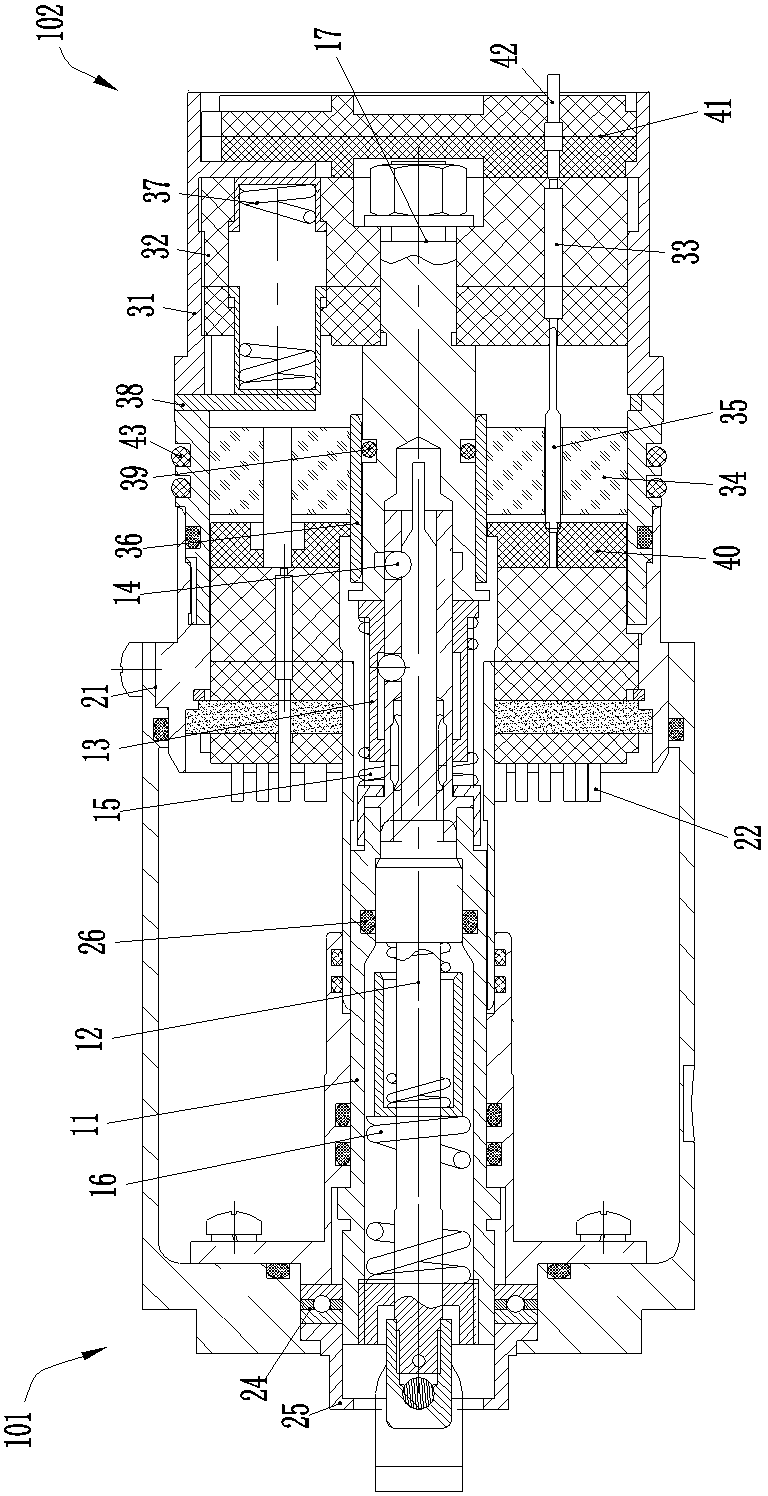
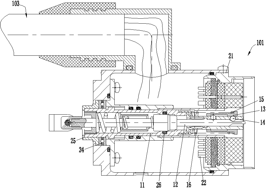
[0029] An embodiment of an underwater separation electrical connector assembly, such as Figure 1-7 As shown, a plug 101 and a socket 102 are included. A mandrel locking mechanism is provided between the plug 101 and the socket 102, and the mandrel locking mechanism includes a mandrel sleeve 11, a mandrel 12, a sliding sleeve 13, a steel ball 14, a pushing spring 15, a locking spring 16 and a lock. Tight circle 17.

[0030] The plug 101 takes the front end as the plug-in end, and it is connected with the corresponding underwater cable 103 during use, including the plug housing 21 and the plug contact 22, the mandrel sleeve 11 of the mandrel locking mechanism, the mandrel 12, the slide The sleeve 13 , the steel ball 14 , the pushing spring 15 and the locking spring 16 are located in the plug housing 21 , wherein the mandrel sleeve 11 can slide back and forth in the plug housing 21 . The plug housing 21 is also equipped with a rotating part (not shown in the figure), and the r...


PUM


Abstract

The invention relates to the field of electric connectors, in particular to an underwater separation electric connector and a plug thereof. The plug comprises a plug casing, wherein a mandrel casing pipe, a mandrel, a sliding sleeve, a steel ball, a pushing and pressing spring and a locking spring are arranged in the plug casing; a rotating part is also arranged on the plug casing; the mandrel casing pipe is arranged in the plug casing in a laterally slidable manner; the rotating part and the mandrel casing pipe form a lead screw nut mechanism for driving an adapted locking ring to reciprocate; a sealing section is arranged on one of the mandrel and the mandrel casing pipe; a sealing matched structure is arranged on the other one of the mandrel and the mandrel casing pipe; the sealing section and the sealing matched structure are mutually matched to block off the front part and the rear part of an inner hole in the mandrel casing pipe; and when the mandrel casing pipe and the adopted locking ring are unlocked and continuously pull the mandrel backwards, the sealing section and the sealing matched structure are staggered at the front part and the rear part and two ends of the inner hole in the mandrel casing pipe are communicated. According to the underwater separation electric connector assembly, the pressure relief separation is realized and the prevention of short circuit in the process that a socket is separated from the plug and after the socket is separated from the plug can be also realized.

Description

technical field [0001] The invention relates to the field of electric connectors, in particular to an underwater separation electric connector assembly and a plug thereof. Background technique [0002] The electrical connector assembly with the mandrel locking mechanism has been widely used due to its characteristics of easy operation, reliable locking and remote unlocking. For example, the electrical connectors or electrical connector assemblies disclosed in Chinese patents with application numbers of 2006201337066, 2009101025876, 2010102038113, 2011203736752, 2011203734371 and 2011205725131 all use the mandrel locking mechanism. [0003] The mandrel locking mechanism mainly includes a mandrel, a mandrel sleeve, a sliding sleeve, a locking spring, a pushing spring, a steel ball and a locking ring. Wherein mandrel, mandrel sleeve pipe, sliding sleeve, locking spring, pushing spring and steel ball mostly are assembled on the plug, and locking ring is assembled on the socket....

Claims


Application Information

Patent Timeline
IPC IPC(8): H01R13/635H01R13/523
Inventor 陈继利
Owner CHINA AVIATION OPTICAL-ELECTRICAL TECH CO LTD
Why Eureka
Try Eureka