Timing control circuit of pulse power supply

A timing control circuit and pulse power supply technology, applied in the direction of high-efficiency power electronic conversion, conversion equipment without intermediate conversion to AC, climate sustainability, etc., can solve the problem of increasing circuit complexity, failing to meet the timing requirements of input power, and circuit failure Satisfy the shutdown timing requirements and other issues, achieve the effect of simple circuit, solve the problem of overcurrent and short circuit protection, and reduce the size of the circuit

Active Publication Date: 2013-09-04
NO 24 RES INST OF CETC
View PDF5 Cites 21 Cited by
  • Summary
  • Abstract
  • Description
  • Claims
  • Application Information

AI Technical Summary

Problems solved by technology

However, 1) due to the use of a comparator, it is necessary to supply power to the comparator, especially when the two output voltages are low, an additional power supply circuit is required, which increases the complexity of the circuit; 2) the circuit cannot meet the requirements of shutdown Timing requirements, using this circuit to design to meet the GaAs FET power supply, can not meet the timing requirements when the input power is turned off

Method used


Image

  • Timing control circuit of pulse power supply
  • Timing control circuit of pulse power supply
  • Timing control circuit of pulse power supply

Examples


Embodiment Construction

[0035] The specific implementation manners of the present invention are not limited to the following description, and are now further described in conjunction with the accompanying drawings.

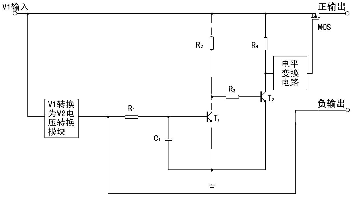
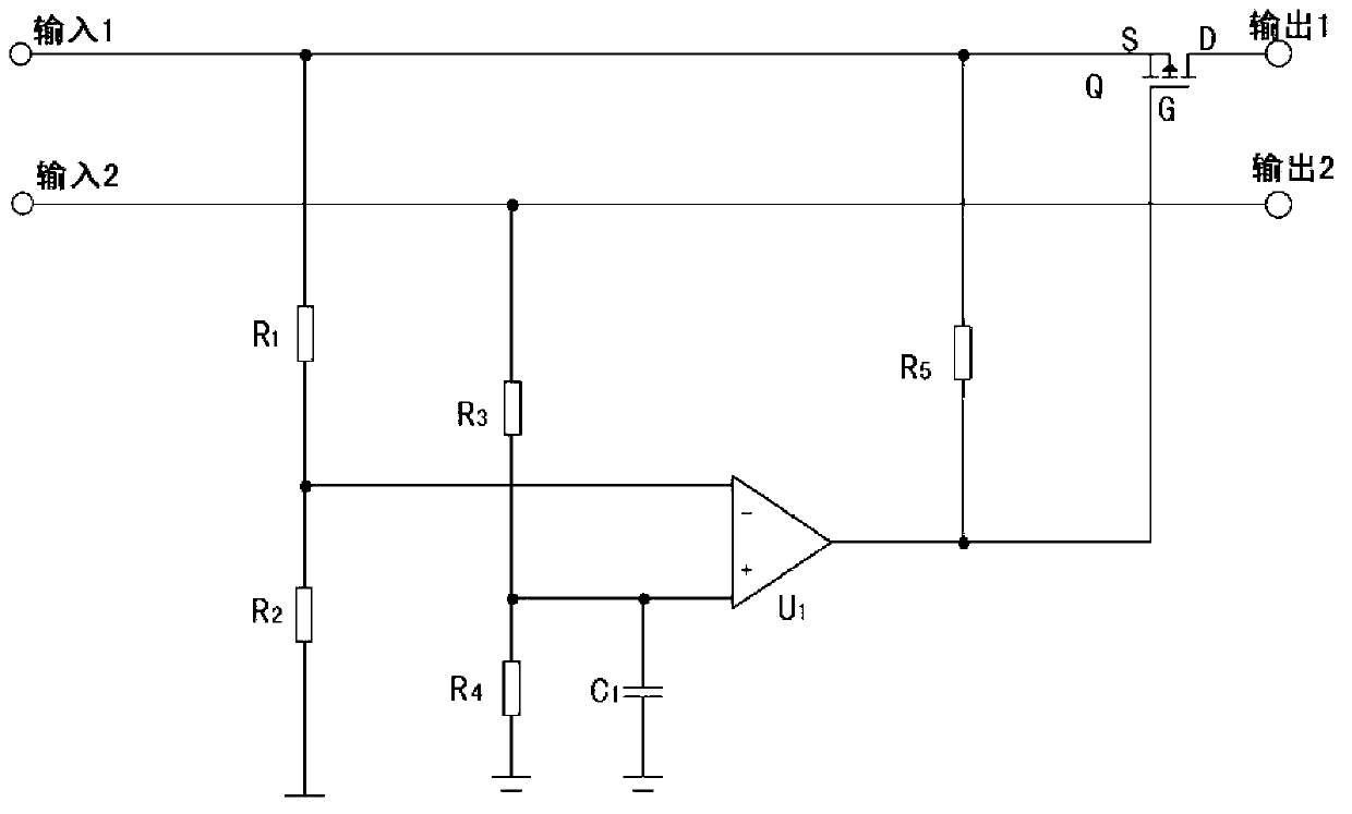
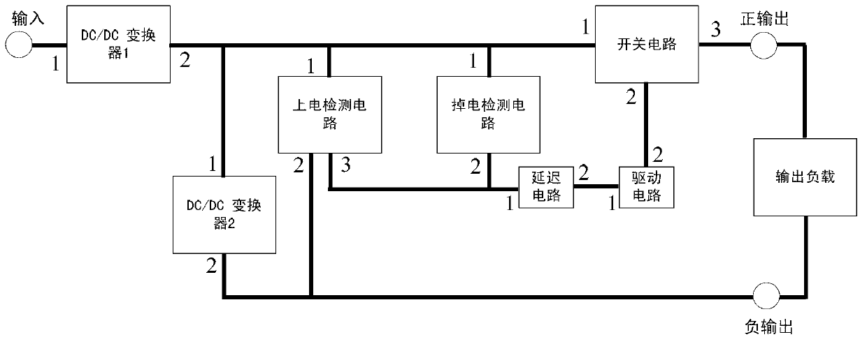
[0036] The structural block diagram of the timing control circuit of the pulse power supply of the present invention is as follows image 3 Shown, the circuit diagram of the timing control circuit of the pulse power supply of the present invention is as Figure 4 As shown, it is composed of DC / DC converter 1, DC / DC converter 2, power-on detection circuit, delay circuit, power-down detection circuit, switching current and driving circuit. Its specific structure, connection relationship and function relationship are similar to those of this The content of the invention in the description is partly the same and will not be repeated here. It works like this:

[0037] Figure 4 , when the input power is turned on: the DC / DC converter 1 starts to work, and its output voltage rises slowly fr...


PUM


Abstract

The invention relates to a timing control circuit of a pulse power supply. The timing control circuit comprises a DC/DC (Direct Current) converter 1, a DC/DC converter 2, a power-on detection circuit, a delay circuit, a power-down detection circuit, switching current and a drive circuit. The power-on timing problems of GaAs devices and the like are solved by fewer components. The power-down timing circuit solves the damage problems of the GaAs devices and the like caused by timing abnormity due to output power-down. The power-down timing circuit is combined with the delay circuit, so that the output overcurrent or short-circuit protection problems of positive voltage are simultaneously solved. The timing control circuit provided by the invention can be widely applied to electronic circuits which need to meet positive and negative power supply timing in the fields of communications, radar, aviation, electronic countermeasure and the like.

Description

technical field [0001] The invention relates to a timing control circuit, in particular to a timing control circuit of a pulse power supply, which is directly applicable to electronic circuits that need to meet positive and negative power supply timing in the fields of communication, radar, aviation, and electronic countermeasures. Background technique [0002] With the development of radio frequency technology, pulsed output voltage is usually used to power radio frequency circuits. Radio frequency devices put forward higher requirements on the switching timing of switching power supplies: a large number of GaAs FETs are used in radio frequency circuits, and signal transmission is completed by modulating the drain voltage of GaAs FETs. Gallium arsenide field effect transistor is a depletion device, and when its gate voltage is 0V, the device is also in a fully conducting state. Therefore, when powering GaAs devices, it is required that the negative gate voltage always prec...

Claims


Application Information

Patent Timeline
Patent Type & Authority Applications(China)
IPC IPC(8): H02M3/10
CPCY02B70/10
Inventor 廖建军尹华鄢毅之余海生李建仁王健安崔庆林
Owner NO 24 RES INST OF CETC
Why Eureka
Try Eureka