Quick milk preparing component
A fast milk making technology, applied in feeding bottles and other directions, can solve problems such as milk powder residue and milk powder compaction
- Summary
- Abstract
- Description
- Claims
- Application Information
AI Technical Summary
Problems solved by technology
Method used
Image
Examples
Embodiment 1
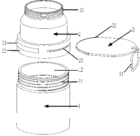
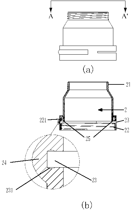
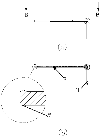
[0049] figure 1 FIG. 3 is a schematic diagram of the quick milk preparation assembly according to Embodiment 1 of the present invention. Such as figure 1 As shown, the quick milk assembly includes a feeding bottle 1, a milk powder box 2 and an insert plate 3. The first connecting part 21 provided on the upper part of the milk powder box 2 is an external thread for threaded connection with the nipple cover, and the second connecting part 21 provided on the lower part The connecting part 22 is an internal thread, and is connected with the third connecting part 11 that is provided with an external thread on the top of the feeding bottle 1; It is the bottom of the milk powder box 2 when in contact, and it can also be pulled out simultaneously. The second connecting portion 22 on the milk powder box is provided with two inserting plate openings, the two inserting plate openings are symmetrical along the diameter axis of the second connecting portion 22, and a flange 24 is provide...
Embodiment 2
[0054] Figure 4 Fig. 6 is a schematic diagram of the quick milk preparation assembly according to the second embodiment of the present invention. Such as Figure 4 As shown, the quick milk assembly includes a feeding bottle 1, a milk powder box 2 and an insert plate 3. The first connecting part 21 provided on the upper part of the milk powder box 2 is a port directly connected to the nipple, and the second connecting part 22 provided on the lower part is The internal thread is connected with the third connection part 11 provided on the upper part of the feeding bottle; the insert plate 3 is used as the movable box bottom of the milk powder box 2, and when inserted into the insert plate opening 23 until it contacts the inner wall of the flange 24, it becomes the bottom of the milk powder box 2 , and can also be pulled out. The second connecting portion 22 on the milk powder box is provided with two inserting plate openings, the two inserting plate openings are symmetrical al...
Embodiment 3
[0058] Figure 7 9 is a schematic diagram of the quick milk preparation assembly according to Embodiment 3 of the present invention. The structure of the milk preparation assembly of the third embodiment and the milk preparation assembly of the first embodiment are basically the same, the difference between the two lies in, for example Figure 7 with Figure 8A As shown, the lower surface of the inserting plate 3 in the milk preparation assembly is provided with a limiting protrusion 33 , and correspondingly, at the inserting plate opening 23 on the milk powder box 2 is provided a gap matching the limiting protrusion 33 . Such as Figure 8B As shown, when the milk brewing assembly is ready to brew, the limit protrusion 33 just inserts into the gap and blocks the thread of the third connecting part 311, and prevents the thread from continuing to advance, and its function is to control the milk brewing assembly when it is ready to brew. The contact strength between the upper ...
PUM
 Abstract
Description
Claims
Application Information
 - R&D
- Intellectual Property
- Life Sciences
- Materials
- Tech Scout
- Unparalleled Data Quality
- Higher Quality Content
- 60% Fewer Hallucinations
Browse by: Latest US Patents, China's latest patents, Technical Efficacy Thesaurus, Application Domain, Technology Topic, Popular Technical Reports.
© 2025 PatSnap. All rights reserved.Legal|Privacy policy|Modern Slavery Act Transparency Statement|Sitemap|About US| Contact US: help@patsnap.com


