Clamping mechanism for precision injection molding machine

An injection molding machine and mold clamping technology, which is applied in the field of plastic product molding, can solve the problems of four guide columns affecting mold accuracy, unreasonable structural frame setting, and difficulty in increasing control, so as to improve mechanical performance and economic benefits, Conducive to high-speed operation and shortened operation time

Inactive Publication Date: 2013-09-11
上海云静企业发展有限公司
View PDF6 Cites 3 Cited by
  • Summary
  • Abstract
  • Description
  • Claims
  • Application Information

AI Technical Summary

Problems solved by technology

The disadvantages of this structure are: firstly, the setting of the structural frame is unreasonable. Wear and tear, the uneven wear of the four guide pillars and the unadjustable structure further affect the accuracy of mold closing; the guide pillars are connected with the fixed template and the rear template to form a rigid structure frame fixed on the machine base of the injection molding machine, because the guide pillars not only guide but also Under the locking force, the deformation caused by the force cannot be compensated, which also affects the accuracy of the model closure; second, the power cylinder undertakes the dual functions of fast movement and clamping, which has both fast and slow movements. A booster cylinder is additionally added, and the plunger or piston rod of the booster cylinder also moves together when the movable template is opened and closed, so that the whole system becomes very complicated, which not only increases the difficulty of control, but also increases the number of equipment parts and fuel tanks. Increased volume, increased exercise load, resulting in increased overall cost, high energy consumption, and low work efficiency
The lack of the above two points has become a bottleneck restricting the further development of injection molding machines

Method used


Image

  • Clamping mechanism for precision injection molding machine
  • Clamping mechanism for precision injection molding machine
  • Clamping mechanism for precision injection molding machine

Examples


Embodiment Construction

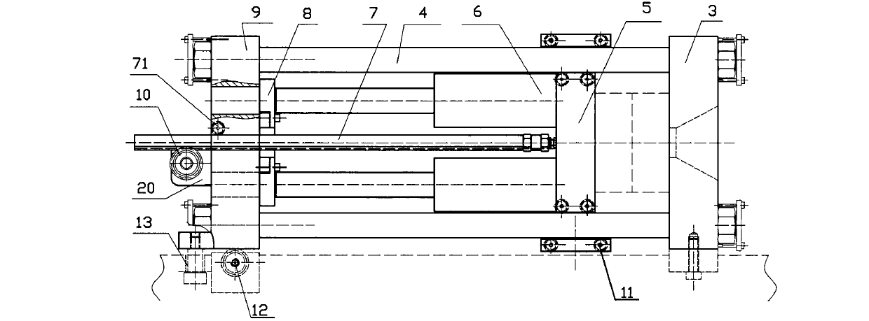
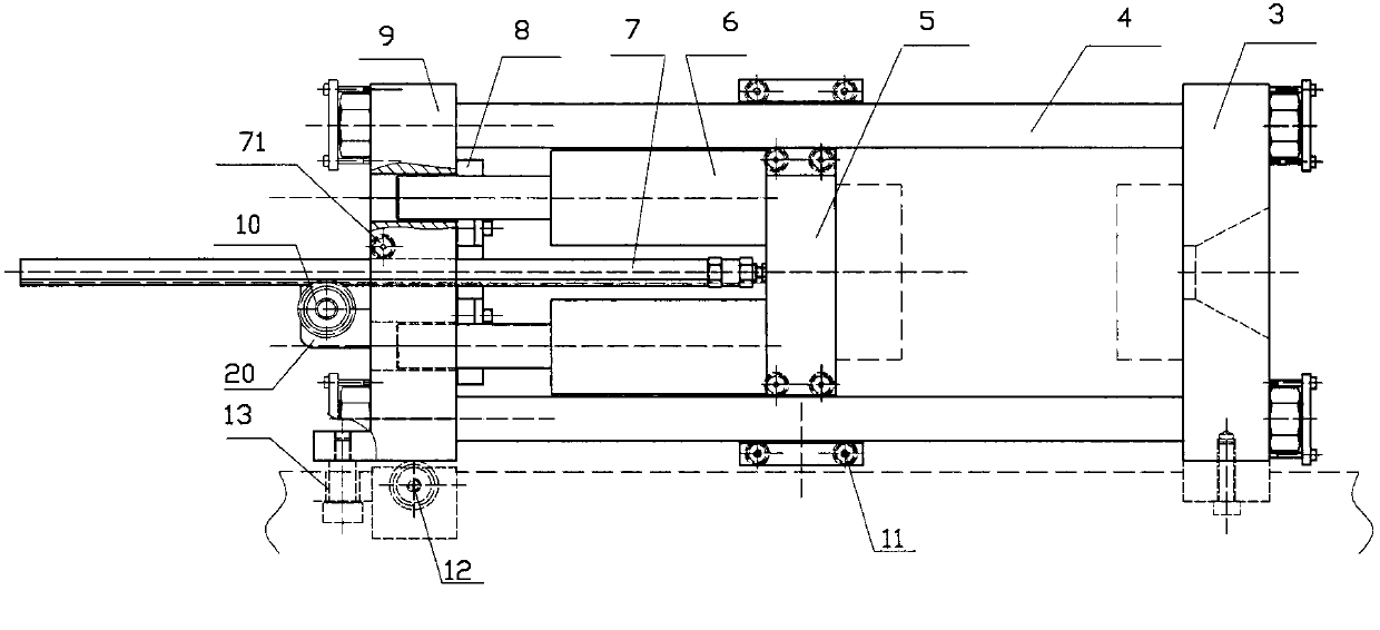
[0016] The specific implementation will be described in detail below in conjunction with the accompanying drawings: Figure 1 ~ Figure 3 In the figure of an embodiment of the present invention shown, a precision injection molding machine clamping mechanism includes: a structural frame composed of a fixed template 3, a movable template 5, a rear template 9, and a guide post 4, and the guide post 4 is located on Between the fixed template 3 and the rear template 9, the movable template 5 is set on the guide post 4 and can slide along the guide post, and there is also a fast moving mechanism for the movable template and a clamping cylinder mechanism; wherein:

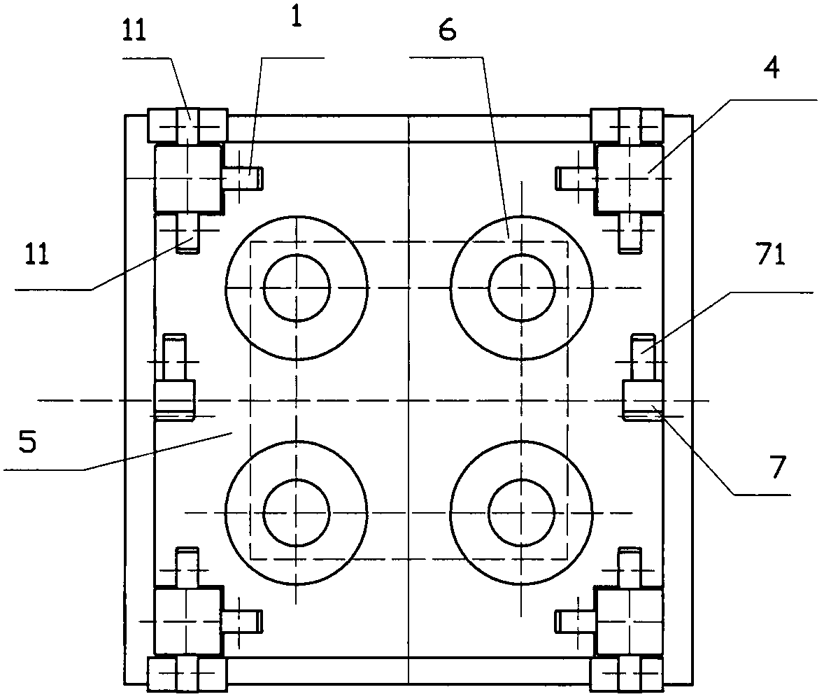
[0017] The cross-section of the guide column 4 of the structure frame is rectangular, and the four corners of the movable template 5 are provided with rollers 11 on the upper / lower cylinder surface of the guide column, and the inner surface of the guide column 4 is provided with a roller 1; The four corners are all provide...


PUM


Abstract

The invention relates to a clamping mechanism for a precision injection molding machine. The clamping mechanism comprises a structure frame composed of a fixed die plate, a movable die plate, a rear die plate and a guide column, a movable die plate fast moving mechanism and a clamping cylinder structure; the section of the guide column on the structure frame is rectangular, four corner parts of the movable die plate are provided with rollers on the upper column surface, the lower column surface and the inner side of the guide column; the movable die plate fast moving mechanism is composed of a motor reduction gear, a pair of engaged gears and rack and a guide wheel; the clamping cylinder structure is composed of four cylinders, a clamping support plate and a transmission mechanism, and the rear die plate has a through hole through which a cylinder piston rod is capable of passing. The clamping mechanism provided by the invention has the advantages that the friction between the movable die plate and the guide column is changed as the rolling friction from the sliding friction, the fit clearance is adjustable, the movement precision is improved, the movement resistance is decreased, and the energy consumption is reduced; through the rotation of the clamping support plate, the length of the guide column required for die closing is greatly shortened through the support or discharging provided for the cylinder piston rod, the whole machine body is reduced, and the control is simplified.

Description

Technical field: [0001] The invention relates to the molding of a plastic product, in particular to a mold locking mechanism of a precision injection molding machine. Background technique: [0002] The clamping mechanism of the injection molding machine needs high-speed mold shifting to shorten the molding cycle, and also requires a large force to clamp the mold. In order to meet these requirements, the structure of the traditional injection molding machine is roughly as follows, including: a fixed platen, a movable platen, and a rear Structural frame composed of formwork and guide pillars, and a power cylinder that transmits movement and locking force; the guide pillars in the structural frame are set between the fixed formwork and the rear formwork, and the movable formwork is set on the guide pillars and can slide along the guide pillars Moving, the cylinder body of the power cylinder is fixed on the rear template or the fixed template, and the plunger or piston rod of th...

Claims


Application Information

Patent Timeline
Patent Type & Authority Applications(China)
IPC IPC(8): B29C45/68
Inventor 章志新
Owner 上海云静企业发展有限公司
Why Eureka
Try Eureka