
Hydraulically-driven variable-area T-shaped anti-rolling hydrofoil

A driving and variable technology, which is applied in the direction of using hydrofoils to reduce the movement of ships on the surrounding water surface, and can solve the problems of weak ship swaying ability, poor anti-rolling effect of hydrofoils, and increased fuel consumption, etc., to achieve The effect of reducing fuel consumption, increasing lift coefficient, and increasing speed

Inactive Publication Date: 2013-09-11
哈尔滨哈船减摇自动化设备有限公司
View PDF8 Cites 26 Cited by
  • Summary
  • Abstract
  • Description
  • Claims
  • Application Information

AI Technical Summary

Problems solved by technology

However, the hydrofoil will generate a lot of resistance when the ship sails at high speed, resulting in a decrease in ship speed and an increase in fuel consumption; while the speed of water flowing through the hydrofoil is low when the ship sails at low speed, if the size of the hydrofoil is small, it will inhibit the ship. The ability to shake is not strong, resulting in poor anti-rolling effect of the hydrofoil when sailing at low speed

Method used


Image

  • Hydraulically-driven variable-area T-shaped anti-rolling hydrofoil
  • Hydraulically-driven variable-area T-shaped anti-rolling hydrofoil
  • Hydraulically-driven variable-area T-shaped anti-rolling hydrofoil

Examples


Embodiment Construction

[0018] Specific embodiments of the present invention are given below and described in conjunction with the accompanying drawings.

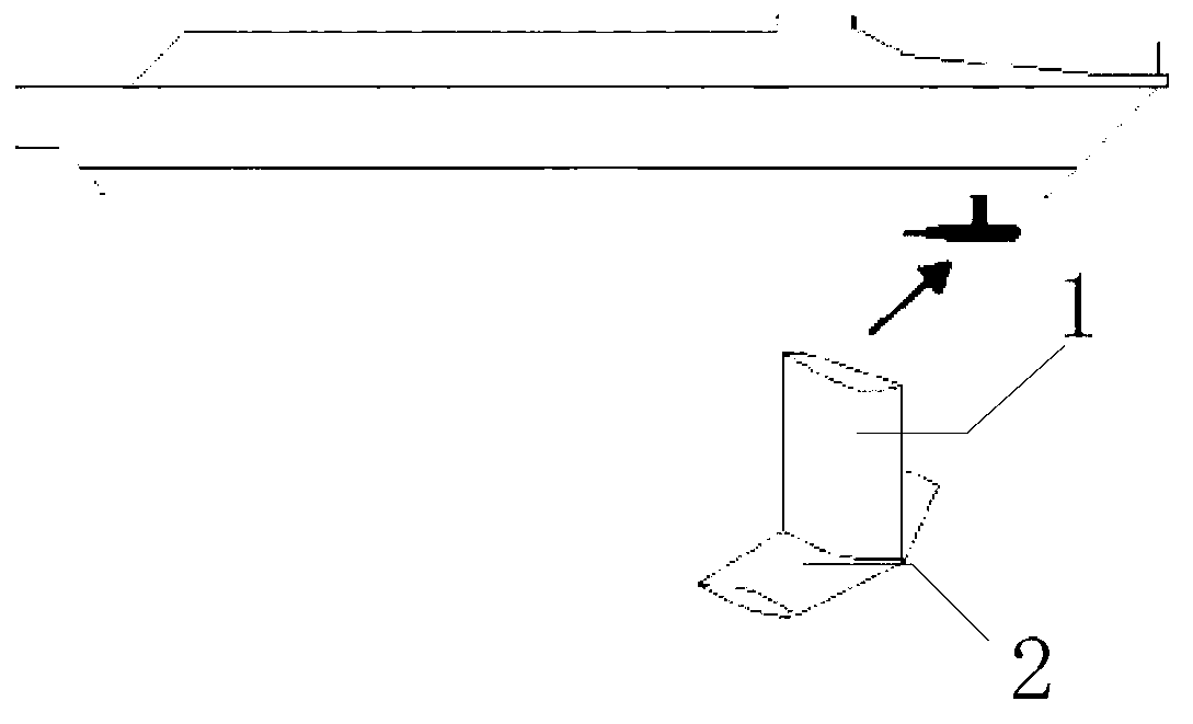
[0019] like figure 1 As shown, the upper end of the column 1 of the T-shaped hydrofoil is fixed on the bottom of the ship; the lower end is connected to the horizontal main wing 2; the column 1 is perpendicular to the horizontal main wing 2.

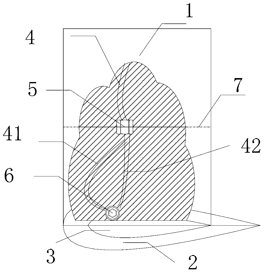
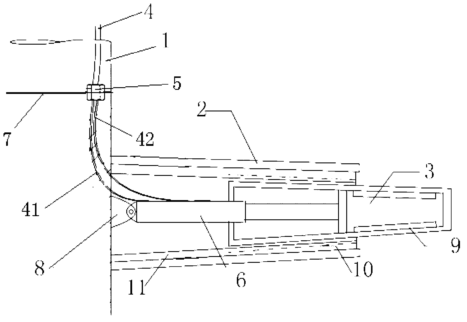
[0020] like figure 2 As shown, the middle part of the column 1 is provided with a sealing baffle 7, and the sealing baffle 7 is provided with an oil hole, and a pipe joint 5 is installed at the oil hole, and the oil pipe 4 is connected with the oil inlet pipe 41 and the oil return pipe 42 through the pipe joint. Horizontal main wing 2 and aileron 3 needn't be sealed; Actuating oil cylinder 6 and oil inlet pipe 41 and oil return pipe 42 all adopt waterproof parts. Horizontal main wing 2 and aileron 3 and column 1 bottom always work in water.

[0021] refer to image 3 and Figure 4 , in order to increas...


PUM


Abstract

A T-shaped hydrofoil capable of changing wing area and aspect ratio comprises a column, a horizontal main wing and extensible auxiliary wings. The upper end of the column is fixed at the hull bottom, and the lower end thereof is connected with the horizontal main wing. When needed, the auxiliary wings are pushed out from auxiliary wing tanks of the horizontal main wing by the aid of hydraulic oil cylinders, so that larger wing area and higher aspect ratio are obtained, lift coefficient is increased, and effects of restraining pitching and heaving are enhanced; when not needed, the auxiliary rings are recovered into the horizontal main wing by the aid of the hydraulic oil cylinders so as to reduce resistance, and accordingly fuel can be saved while speed is increased.

Description

technical field [0001] A hydraulically driven variable-area T-shaped anti-rolling hydrofoil, which is used to equip high-speed ships (such as single wave piercing craft, high-speed monohull or high-speed trimaran, etc.); it belongs to the shrinkable or folding hydrofoil of ships field. technical background [0002] The pitch and heave of the ship have many adverse effects on the navigation of the ship, especially for high-speed ships. In order to solve this problem, it is widely used to install T-shaped hydrofoils at the bottom of the bow. The working principle of the T-shaped hydrofoil is to use the hydrofoil to generate lift to restrain the pitching moment and heave force of the hull, and play the role of anti-rolling. However, the hydrofoil will generate a lot of resistance when the ship sails at high speed, resulting in a decrease in ship speed and an increase in fuel consumption; while the speed of water flowing through the hydrofoil is low when the ship sails at low ...

Claims


Application Information

Patent Timeline
IPC IPC(8): B63B39/06
Inventor 梁利华张松涛王广雨文禹姜见龙王经甫吉明
Owner 哈尔滨哈船减摇自动化设备有限公司
Learn More