
Multistage rotary-wheel dehumidification device with auxiliary heat rejection and application method thereof

A rotary dehumidification and rotary wheel technology, applied in heating methods, applications, household heating, etc., can solve problems such as increasing the complexity of the device and affecting the energy efficiency level of the device, achieving efficient operation, flexible design and use, and reducing energy consumption. The effect of matching loss

Inactive Publication Date: 2013-09-11
TSINGHUA UNIV
View PDF10 Cites 14 Cited by
  • Summary
  • Abstract
  • Description
  • Claims
  • Application Information

AI Technical Summary

Problems solved by technology

This way of setting the two-stage condensers 101, 102 helps to discharge the heat of condensation better, but the complexity of the device is increased due to the two-stage air duct for adjusting the air volume of the regeneration air, and the single-stage rotor treatment method It still makes the heat pump work under a large temperature difference, which affects the energy efficiency level of the device
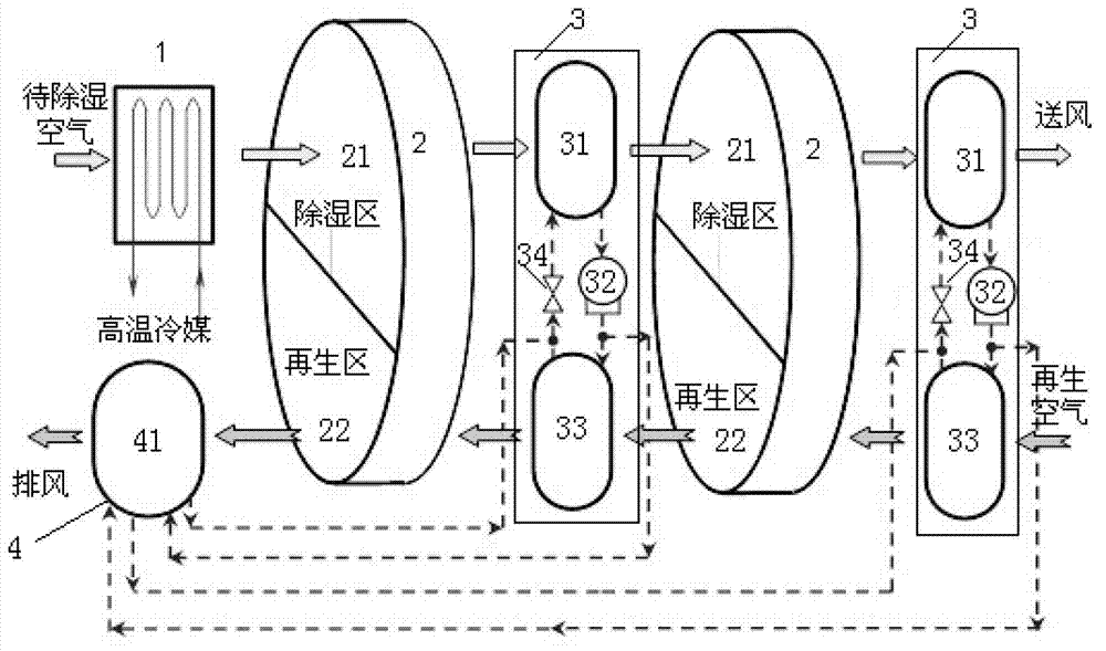
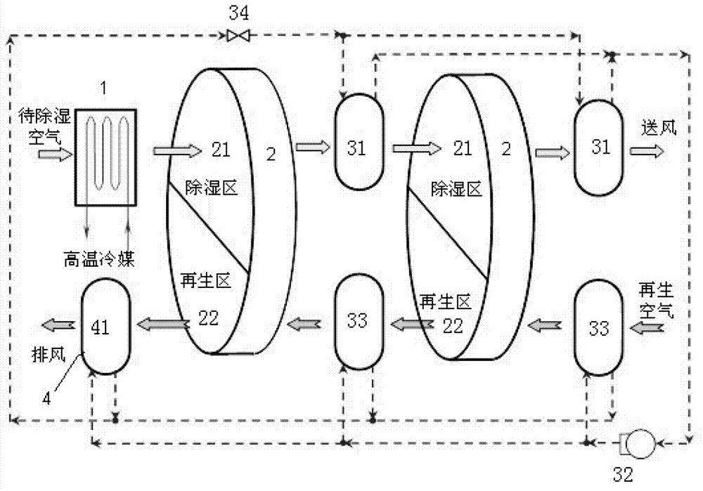
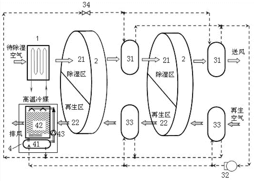
[0005] From the above background technology, there is no heat pump-driven dehumidification air treatment device with auxiliary heat removal at present. Therefore, a high-temperature cold source that independently controls the temperature and humidity of the air-conditioning system is proposed to pre-cool the fresh air to be treated. , The solid dehumidification air treatment device that uses heat pump circulation heat to meet the regeneration requirements of the runners. The dehumidification runners are set in stages to reduce the regeneration temperature requirements, and the auxiliary cooling device is set to eliminate excess condensation heat. It is suitable for the air conditioning system with independent temperature and humidity control, which can be better Meet the needs of indoor humidity regulation and realize the efficient operation of air handling units

Method used


Image

  • Multistage rotary-wheel dehumidification device with auxiliary heat rejection and application method thereof
  • Multistage rotary-wheel dehumidification device with auxiliary heat rejection and application method thereof
  • Multistage rotary-wheel dehumidification device with auxiliary heat rejection and application method thereof

Examples


Embodiment Construction

[0017] The present invention will be described in detail below in conjunction with the accompanying drawings and embodiments.

[0018] Such as figure 1 As shown, the device of the present invention includes a pre-cooling treatment unit 1 , a solid moisture absorbent runner 2 , a heat pump circulation unit 3 and an auxiliary cooling device 4 .

[0019] The pre-cooling treatment unit 1 of the present invention is a heat exchanger with heat exchange tubes, and the refrigerant or cold water in the heat exchange tubes is a high-temperature refrigerant for an air-conditioning system with independent temperature and humidity control.

[0020] The solid hygroscopic agent runner 2 of the present invention is a prior art, and it includes two stages arranged at intervals, and each stage of the runner 2 is driven by a driving device to rotate slowly, and the solid hygroscopic agent positioned on the air supply path is used as a dehumidification zone 21, Realize the dehumidification proc...


PUM


Abstract

The invention relates to a multistage rotary-wheel dehumidification device with auxiliary heat rejection and an application method thereof. The device comprises a precooling processing unit, solid hygroscopic agent rotary wheels, heat pump circulating units and an auxiliary cooling device, wherein the precooling processing unit is a heat exchanger provided with a heat exchange pipe; refrigerant or cold water in the heat exchange pipe is high temperature refrigerant of a temperature and humidity independent control air condition system; the solid hygroscopic agent rotary wheels comprise two stages arranged at an interval; each stage of rotary wheel comprises a dehumidification area positioned on an air supply path and a regenerating area positioned on an air exhaust path; the heat pump circulating units comprise two evaporators arranged in parallel and two condensers arranged in parallel; each evaporator is arranged on the air supply path at the rear part of the dehumidification area of each stage of rotary wheel; each condenser is arranged at the inlet end of the air exhaust path of the regenerating area of each stage of rotary wheel; and the auxiliary cooling device is arranged at the outlet end of the air exhaust path of the regenerating area of the first stage of rotary wheel. The multistage rotary-wheel dehumidification device is widely applicable to the requirement for the humidity adjustment of the temperature and humidity independent control air condition system, and can better realize the efficient operation of an air condition system.

Description

technical field [0001] The invention relates to a rotary dehumidification device and its use method, in particular to a multi-stage rotary dehumidification device with auxiliary heat removal and its use method. Background technique [0002] As a new type of air conditioning system, the temperature and humidity independent control air conditioning system adjusts the humidity by sending dry air to bear the indoor humidity load, and uses high temperature (16-18°C) refrigerant (cold water or refrigerant) Waiting to adjust the indoor temperature, this method can not only better realize the adjustment of indoor temperature and humidity, but also can achieve a good energy saving effect. In the air-conditioning system with independent control of temperature and humidity, it is of great significance to select an appropriate humidity treatment method to improve the energy efficiency of the entire air-conditioning system. [0003] Compared with the condensation dehumidification method...

Claims


Application Information

Patent Timeline
Patent Type & Authority Applications(China)
IPC IPC(8): F24F3/147
Inventor 刘晓华张涛涂壤江亿
Owner TSINGHUA UNIV
Learn More