Device and method for direct liquefaction of pipeline natural gas using expander

A technology of liquefied natural gas and expander, which is applied in liquefaction, refrigeration, liquefaction, solidification, etc., can solve the problems of high liquefaction rate, unreachable natural gas, complex process structure, etc., and achieve the effect of low cost, less equipment and simple process

Active Publication Date: 2016-03-02
合肥万豪能源设备有限责任公司
View PDF8 Cites 0 Cited by
  • Summary
  • Abstract
  • Description
  • Claims
  • Application Information

AI Technical Summary

Problems solved by technology

The utility model patent with the Chinese Patent Publication No. CN202432824U discloses a differential pressure liquefaction device that increases the liquefaction rate by adding an external energy source at the front. The downside of the technology is that additional energy is required to liquefy natural gas
The utility model patent with the Chinese Patent Publication No. CN202393170U discloses an energy-saving liquefaction device with dual circuits and double expanders in the natural gas transmission trunk line. However, the device has a complex process structure and has the disadvantage of not being able to achieve a higher liquefaction rate for pipeline natural gas with lower pressure

Method used


Image

  • Device and method for direct liquefaction of pipeline natural gas using expander

Examples


Embodiment 1

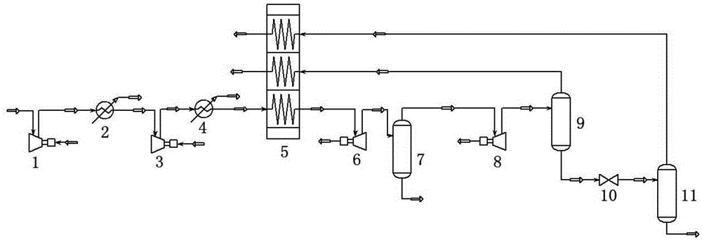
[0039]This embodiment relates to a device for directly liquefying pipeline natural gas by using an expander. The device consists of a first-stage supercharger, a first-stage water cooler, a second-stage supercharger, a second-stage water cooler, and a main heat exchanger , a first-stage expander, a heavy hydrocarbon separator, a second-stage expander, a first-stage gas-liquid separator, a throttle valve and a second-stage gas-liquid separator, and its structure is as follows figure 1 shown.

[0040] This embodiment also relates to a method for preparing liquefied natural gas using the aforementioned device, the method comprising the following steps:

[0041] Step 1, divide the molar composition into 94% CH 4 , 4%C 3 h 8 and 2%N 2 , Natural gas with a pressure of 4.5MPa, a temperature of 35°C and a flow rate of 1kmol / h is boosted to 6.33MPa by a two-stage supercharger, and then cooled to 40°C by a two-stage water cooler;

[0042] Step 2, the natural gas cooled in step 1 en...

Embodiment 2

[0048] This embodiment relates to a device for directly liquefying pipeline natural gas by using an expander. The device consists of a first-stage supercharger, a first-stage water cooler, a second-stage supercharger, a second-stage water cooler, and a main heat exchanger , a first-stage expander, a heavy hydrocarbon separator, a second-stage expander, a first-stage gas-liquid separator, a throttle valve and a second-stage gas-liquid separator, and its structure is as follows figure 1 shown.

[0049] This embodiment also relates to a method for preparing liquefied natural gas using the aforementioned device, the method comprising the following steps:

[0050] Step 1, divide the molar composition into 94% CH 4 , 4%C 3 h 8 and 2%N 2 , Natural gas with a pressure of 5.0MPa, a temperature of 35°C and a flow rate of 1kmol / h is boosted to 7.82MPa by a two-stage supercharger, and then cooled to 40°C by a two-stage water cooler;

[0051] Step 2, the natural gas cooled in step 1 e...


PUM


Abstract

The invention provides a device and method for directly liquefying pipeline natural gas by using an expander. The device is composed of a first-stage booster, a first-stage water cooler, a second-stage device, a first-stage expander, a heavy hydrocarbon separator, a second-stage expander, a first-stage gas-liquid separator, a throttle valve and a second-stage gas-liquid separator; the present invention also relates to the preparation of liquefied natural gas using the aforementioned device Methods. The invention can directly use high-pressure natural gas to enter the expander to realize the liquefaction of part of the natural gas without external energy supply. The liquefaction process flow can realize the liquefaction rate of 10-14% of natural gas through proper parameter adjustment. The method of the invention has simple process, less equipment, high efficiency and low cost, and has good application prospect.

Description

technical field [0001] The invention belongs to the technical field of chemical engineering and cryogenic engineering, and in particular relates to a device and method for directly liquefying pipeline natural gas by using an expander. Background technique [0002] As the main fossil energy in the world, natural gas, oil and coal account for a large proportion of primary energy. Natural gas is a high-quality clean energy, and more and more countries have begun to pay attention to the development and utilization of natural gas resources. [0003] The large-scale transportation of natural gas mainly adopts pipeline transportation. At present, most of the long-distance natural gas in my country is transported by high-pressure pipelines. For example, the pressure of the West-East Gas Pipeline reaches 10MPa. It is supplied to users after low pressure. Natural gas pressure regulation usually uses a throttle valve, and a large amount of pressure energy will be lost in the process ...

Claims


Application Information

Patent Timeline
Patent Type & Authority Patents(China)
IPC IPC(8): F25J3/00
CPCF25J1/0022F25J1/0035F25J1/004F25J1/0232F25J2220/64F25J2230/30
Inventor 巨永林贺天彪
Owner 合肥万豪能源设备有限责任公司
Why Eureka
Try Eureka