A regenerative mixed refrigerant gas liquefaction cycle system

A technology of mixed working fluid and circulation system, which is applied in the direction of refrigeration and liquefaction, liquefaction, lighting and heating equipment, etc., and can solve problems such as time-consuming and complicated restart process

Active Publication Date: 2018-11-09
TECHNICAL INST OF PHYSICS & CHEMISTRY - CHINESE ACAD OF SCI
View PDF5 Cites 0 Cited by
  • Summary
  • Abstract
  • Description
  • Claims
  • Application Information

AI Technical Summary

Problems solved by technology

However, the traditional MRC liquefaction process technology also has an insurmountable technical problem: the restart process after each shutdown is quite complicated, which not only requires the operation of very professional personnel and the cooperation of a large number of special instruments and equipment, but also is very time-consuming
However, there is currently no special multi-stage compressor available for small liquefaction plants.

Method used


Image

  • A regenerative mixed refrigerant gas liquefaction cycle system
  • A regenerative mixed refrigerant gas liquefaction cycle system
  • A regenerative mixed refrigerant gas liquefaction cycle system

Examples


Embodiment 1

[0049] Example 1: A basic regenerative mixed working medium refrigeration natural gas liquefaction cycle system

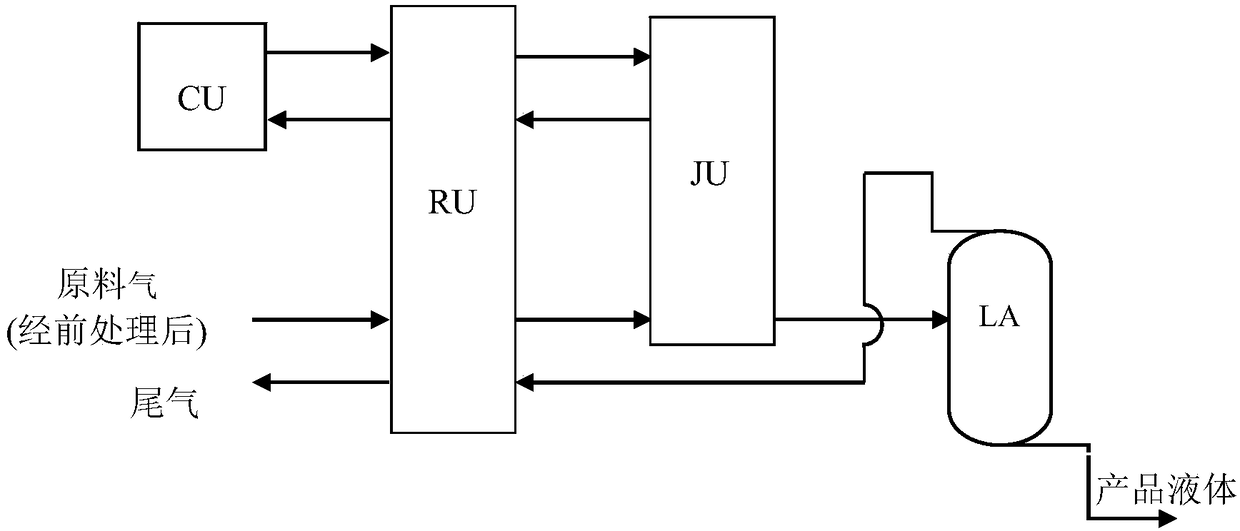
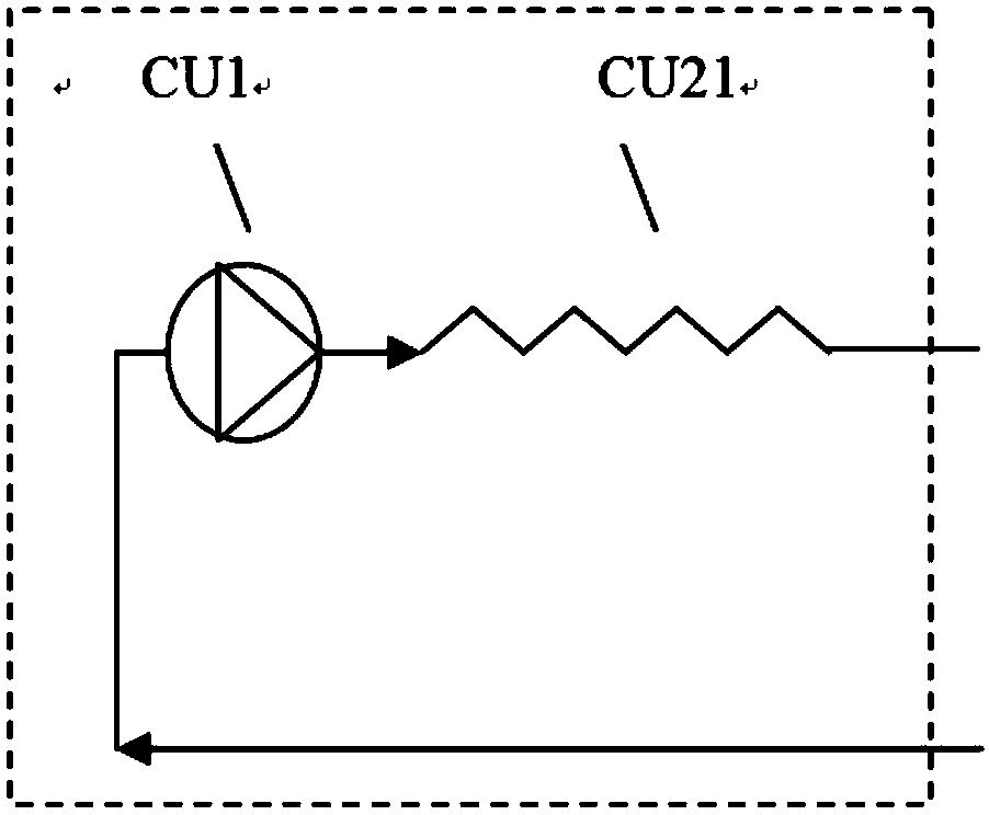
[0050] figure 1 It is a structural schematic diagram of the regenerative mixed refrigerant gas liquefaction cycle system of this embodiment. image 3 It is a structural schematic diagram of a compressor module CU in this embodiment. Figure 4 It is a structural schematic diagram of a regenerative heat exchanger module RU in this embodiment. Figure 5 It is a structural schematic diagram of a throttling module JU of this embodiment.

[0051] The regenerative mixed refrigerant gas liquefaction cycle system provided in this embodiment includes a compressor module CU, a regenerative heat exchanger module RU, a throttling module JU, a liquid storage tank LA, a gas liquefaction circuit and its connecting pipelines and valves . Its connection method is as follows:

[0052] Refrigerant circulation circuit: the high-pressure refrigerant outlet of the compressor module ...

Embodiment 2

[0066] Example 2: A regenerative mixed working medium refrigeration natural gas liquefaction cycle system with a refrigeration working medium buffer adjustment tank and a simple oil separator

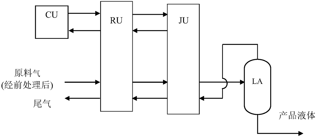
[0067] figure 2 It is a structural schematic diagram of the regenerative mixed refrigerant gas liquefaction cycle system of this embodiment. The compressor module CU consists of Figure 6 and Figure 7 The composition of the structure shown. The regenerative heat exchanger module RU consists of Figure 13 The composition of the structure shown. The throttle module JU consists of Figure 18 The composition of the structure shown. The regenerative mixed refrigerant gas liquefaction cycle system includes a compressor module CU, a regenerative heat exchanger module RU, a throttling module JU, a liquid storage tank LA, a gas liquefaction circuit, connecting pipelines and valves. Its connection method is:

[0068] Refrigerant circulation circuit: the high-pressure refrigerant outlet ...

Embodiment 3

[0082]Example 3: A regenerative mixed working medium refrigeration natural gas liquefaction cycle system with a refrigeration working medium buffer adjustment tank, two-stage oil separator and suction gas-liquid separator

[0083] figure 2 It is a structural schematic diagram of the regenerative mixed refrigerant gas liquefaction cycle system of this embodiment. The compressor module CU consists of Figure 6 , 7 , 11 and 12, the regenerative heat exchanger module RU consists of Figure 15 and Figure 17 Composed of the structure shown, the throttling module JU consists of Figure 18 The composition of the structure shown. The regenerative mixed refrigerant gas liquefaction cycle system consists of compressor module CU, regenerative heat exchanger module RU, throttling module JU, liquid storage tank LA, gas liquefaction circuit and its connecting pipelines and valves. Its connection method is:

[0084] Refrigerant circulation circuit: the high-pressure refrigerant outle...


PUM


Abstract

A regenerative mixed working-medium refrigerating gas liquefaction cycle system comprises a compressor module, a regenerative heat exchanger module and a throttling module, wherein the compressor module comprises a compressor; the regenerative heat exchanger module comprises a segregation separator, a first regenerative heat exchanger, an intermediate throttling element and a second regenerative heat exchanger; the segregation separator is vertically arranged; and the throttling module comprises a refrigerating system throttling regulation valve group and a raw material throttling regulation valve group. The above regenerative mixed working-medium refrigerating gas liquefaction cycle system has the advantages that due to a more complete regenerative process, a perfect oil return system and the segregation separating technology, a refrigerating process can be driven by a single-unit common oil-lubricated compressor driving system, and then low cost and reliability can be achieved; the cycle process layout is flexible, and the regenerative mixed working-medium refrigerating gas liquefaction cycle system can efficiently and widely adapt to the needs of multi-element gas liquefaction-separation and other application occasions with complex-distribution loads; and the regenerative mixed working-medium refrigerating gas liquefaction cycle system is insensitive to a feed gas working condition, and thus such gases as natural gas and coalbed methane can be liquefied at a relatively low pressure.

Description

technical field [0001] The invention relates to a refrigerator in the technical field of refrigeration and low temperature, in particular to a regenerative mixed refrigerant gas liquefaction circulation system. Background technique [0002] The research on natural gas liquefaction devices is a hot spot in the world. The existing coalbed methane / natural gas liquefaction technologies mainly include the following types, and their technical characteristics and development are briefly introduced as follows: [0003] 1) Cascade cascade liquefaction process: This liquefaction process usually adopts three-stage pure working medium cascade refrigeration (cascade cascade), which are three refrigeration units of propane, ethylene and methane, and cascade cooling step by step to realize natural gas cooling and liquefaction. Among them, three different evaporation pressure levels are adopted in each level of pure working fluid cycle, so that up to nine evaporation temperature platforms ...

Claims


Application Information

Patent Timeline
Patent Type & Authority Patents(China)
IPC IPC(8): F25J1/02
CPCF25J1/0204F25J1/0279
Inventor 吴剑峰董学强公茂琼
Owner TECHNICAL INST OF PHYSICS & CHEMISTRY - CHINESE ACAD OF SCI
Why Eureka
Try Eureka