Furnace body of cupola furnace

A technology of cupola and furnace body, applied in furnaces, vertical furnaces, furnace types, etc., can solve the problems of flue gas entering the workshop, damage to the furnace, and large width.

Inactive Publication Date: 2014-09-24
姚立猛 +1
View PDF7 Cites 0 Cited by
  • Summary
  • Abstract
  • Description
  • Claims
  • Application Information

AI Technical Summary

Problems solved by technology

The process of feeding the cupola in the above-mentioned prior art has obvious disadvantages: firstly, the feed barrel of this kind of feeder enters into the cupola through the feed port on the side, and because the height and diameter of the feed barrel are usually large, Coupled with the height of the frame-shaped beam frame of the traveling mechanism of the monorail feeder, the steel rope and the hook, not only the height and width of the feeding port on the side of the cupola are larger (for example, the melting rate is 10 per hour. The feeding port of the cupola up to 12 tons is about 4 to 5 meters high and 1.6 to 1.8 meters wide, and the feeding port of the cupola with a melting rate of 3 tons is 2.5-2.6 meters high, and the width is basically the same as the inner diameter of the furnace) , resulting in more external air being sucked into the inner cavity of the furnace body from the upper space of the charging port during operation of the cupola, and the suction generated by the hot air flow and the fan of the dust removal device is consumed by the entry of the external air at the upper part of the charging port Lose
This type of feeder must cooperate with the transformation of the furnace chimney. It is necessary to install an air induction device on the upper part of the furnace chimney that emits smoke from the side. Although the problem of smoke entering the workshop can be avoided during operation, the structure of this structure The cupola furnace not only requires a large investment and high energy consumption during operation, but also because the position of the feeding port is relatively high (it can reduce the height of the chimney, but it is still higher than the position of the feeding port of ordinary cupolas), it is easy to cause damage to the furnace when feeding. Damage and breakage of coke

Method used


Image

  • Furnace body of cupola furnace
  • Furnace body of cupola furnace
  • Furnace body of cupola furnace

Examples


Embodiment 1

[0095] (Embodiment 1, material guide device)

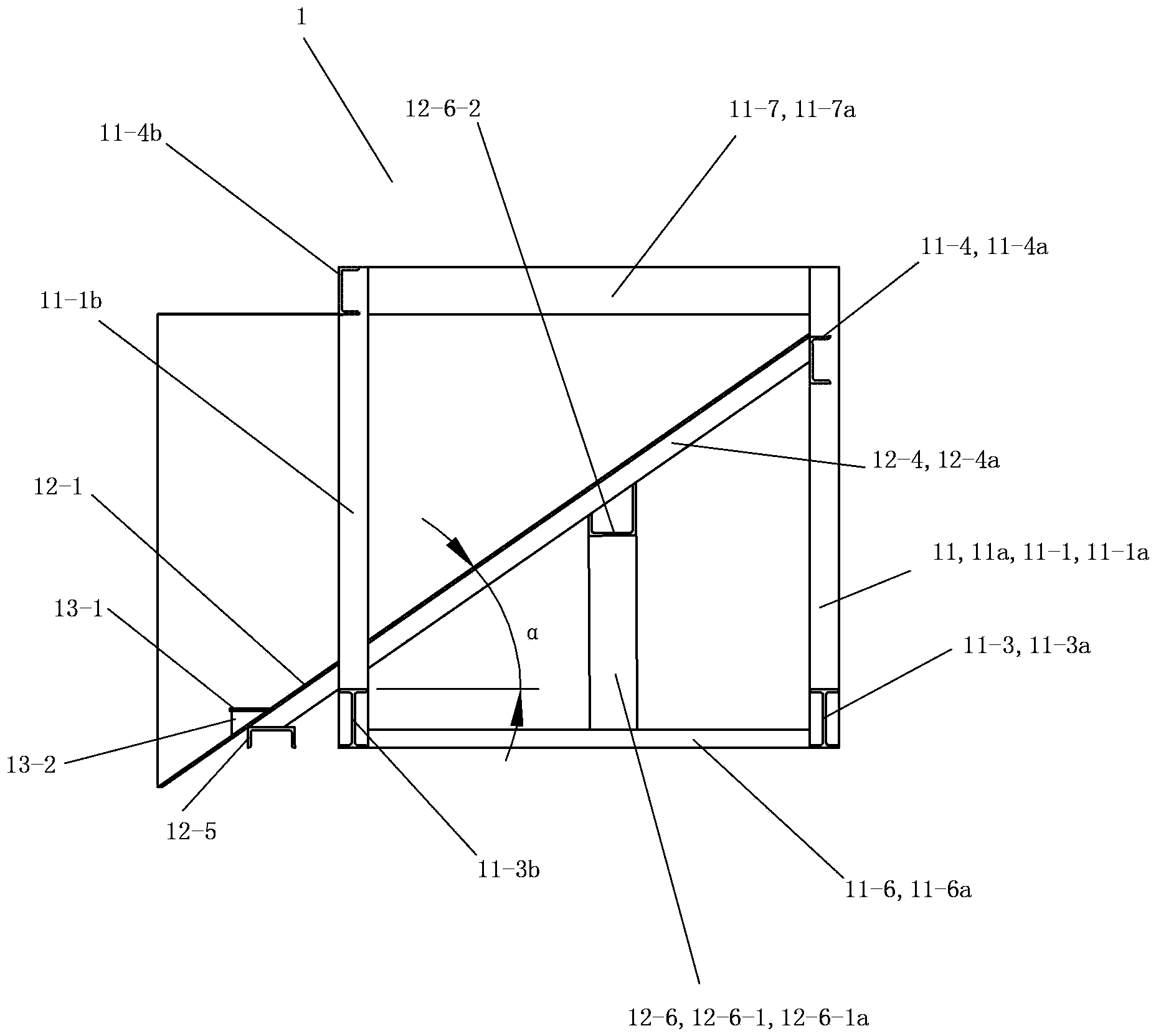
[0096] See Figure 1 to Figure 3 , The material guide device 1 of this embodiment includes a support structure, a material guide structure 12 and a buffer device 13 . The support structure is a wedge-shaped support base or steel structure support frame made of cement and bricks (this embodiment is a support frame composed of straight steel components fixedly connected to each other in sequence, and the straight Steel components are I-beams or / and channel steels or / and angle steels).

[0097] The supporting structure of the material guiding device 1 includes a steel main frame body 11 a as a frame 11 . The main frame body 11a is a structural member in the form of a rectangular parallelepiped frame, and its upper part is open. The material guide structure 12 is fixed on the main frame body 11a in an inclined manner with the front high and the rear low.

[0098] The main frame body 11a includes two left vertical beams 11-1 and tw...

Embodiment 2

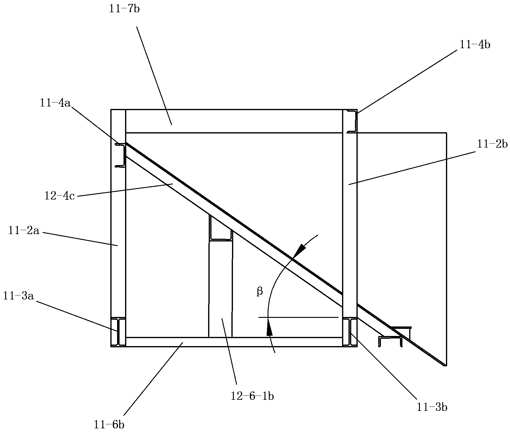
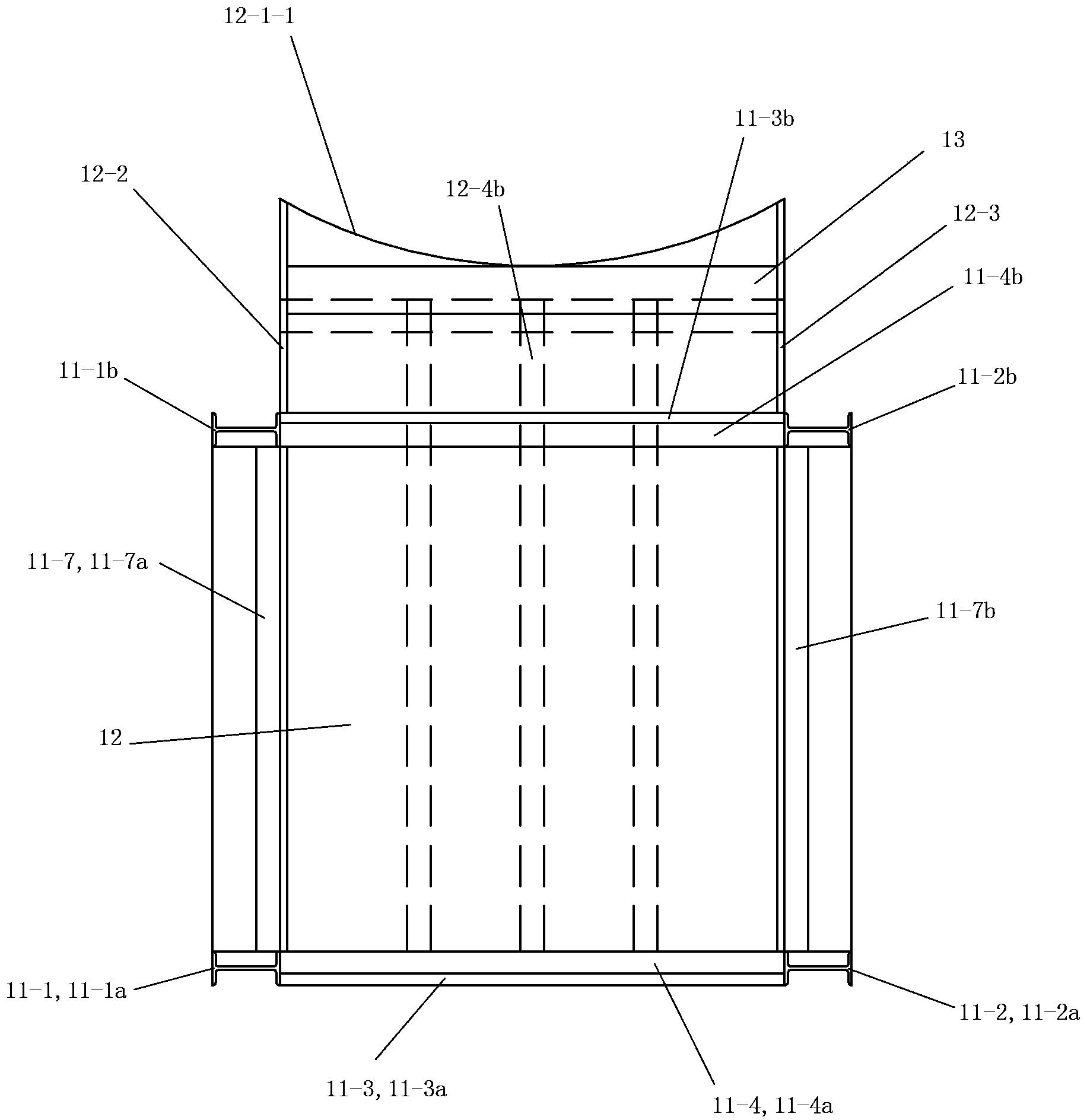
[0114] (Embodiment 2, material guide device)

[0115] See Figure 4 to Figure 6 , The material guide device 1 of this embodiment includes a support structure, a material guide structure 12 and a buffer device 13 . The material guide structure 12 , the buffer device 13 and the connection relationship between the material guide structure 12 and the buffer device 13 in this embodiment are the same as those in the first embodiment. The supporting structure of the material guiding device 1 includes a bracket 11 . The difference between this embodiment and Embodiment 1 lies in that the length of each vertical beam of the bracket 11 in this embodiment is twice the length of each vertical beam in Embodiment 1. The support 11 of the present embodiment is made up of two parts of the main frame body 11a and the barrel support frame 11b, and the lower half of each vertical beam is used as the vertical beam of the main frame body 11a, so that the main frame body 11a of the present embodi...

Embodiment 3

[0124] (embodiment 3, the furnace body of cupola)

[0125] See Figure 7 to Figure 9 and Figure 11 , the furnace body of the cupola of the present invention is a side-feeding type furnace body 2, which includes a furnace bottom part 2a, a hearth part 2b, a furnace body part 2c and a chimney part 2d in order from bottom to top. The supporting part 20 of the cupola includes a foundation, pillars, a furnace floor and a furnace door. The body of furnace 2 is basically in the shape of a circular column, and is the part of the cupola that is located on the furnace floor of the cupola supporting part 20. The upper material is the furnace lining 22 of refractory material, wherein, the part of the furnace lining 22 from the furnace floor to the lower edge of the feeding port is the furnace body 22-1.

[0126] See Figure 12 to Figure 16 , The furnace body 2 also includes a collision protection ring 23 . The collision protection ring 23 is formed by welding and fixing a cylindrica...


PUM

PropertyMeasurementUnit
lengthaaaaaaaaaa
angleaaaaaaaaaa

Abstract

The invention discloses a furnace body of a cupola furnace. Materials are fed into the furnace body laterally. The furnace body sequentially comprises a hearth, a crucible, a stack and a chimney from bottom to top. The furnace body is basically in the shape of a circular column and is positioned on a hearth plate of a cupola furnace supporting portion of the cupola furnace, and a feed inlet of the furnace body is positioned on the lower portion of the chimney. The furnace body mainly comprises a cylindrical shell and a furnace lining, the cylindrical shell is made of steel plates, and the furnace lining made of refractory materials is fixed onto the inner wall of the shell. A combustion chamber is arranged on a part, which is positioned from the hearth plate to the lower edge of the feed inlet, of the furnace lining. The furnace body further comprises a collision protection ring. The furnace body is structurally characterized in that the height of the feed inlet of the furnace body ranges from 400 millimeters to 1500 millimeters, and the width of the feed inlet ranges from 80% to 100% of the inner diameter of the combustion chamber of the furnace body. The collision protection ring is provided with a feeding notch, the feeding notch is positioned at the front of the upper portion of the collision protection ring, and the shape of the feeding notch corresponds to that of the rear of a guide groove of a guide device used with the feeding notch.

Description

[0001] This application is an application number of 201110360226.9, the application date is November 14, 2011, and the invention and creation name is "a material guide device, a furnace body of a cupola furnace, and a furnace body of a cupola furnace with a material guide device". case application. technical field [0002] The invention relates to the field of manufacture of cupolas, in particular to a furnace body of a cupola and corresponding auxiliary devices. Background technique [0003] Cast iron melting is one of the important links to obtain high-quality castings. Cast iron melting equipment includes mixing furnace, three-section furnace, electric furnace (electric arc furnace or induction furnace), cupola and so on. Among them, the cupola furnace is the most widely used, and the total output of cast iron parts exceeds 90%. This is because the cupola melting is characterized by simple equipment, convenient operation, high production efficiency, continuous produc...

Claims


Application Information

Patent Timeline
Patent Type & Authority Patents(China)
IPC IPC(8): F27B1/20
Inventor 姚立猛陈姚
Owner 姚立猛
Why Eureka
Try Eureka