Flow field observing device for oil cavity

A technology of observation device and oil cavity, which is applied in the direction of measuring device, fluid dynamics test, machine/structural component test, etc., can solve the problems of less experimental research, difficult observation, complex flow field structure, etc., and achieve accurate and reliable results , rich results, simple and convenient operation

Inactive Publication Date: 2013-09-11
BEIJING UNIV OF TECH
View PDF6 Cites 7 Cited by
  • Summary
  • Abstract
  • Description
  • Claims
  • Application Information

AI Technical Summary

Problems solved by technology

[0008] Due to the complex structure of this type of flow field, it is greatly affected by external factors, the repeatability is poor, and it is not easy to observe. There are few experimental studies, and there is a lack of such experimental models and observation methods.
Therefore, most of the research on the internal flow field structure of this type of cavity adopts the method of numerical simulation, and the model and boundary conditions are simplified, which cannot truly reflect the actual flow, thus limiting the research on this kind of flow.

Method used


Image

  • Flow field observing device for oil cavity
  • Flow field observing device for oil cavity
  • Flow field observing device for oil cavity

Examples


Embodiment Construction

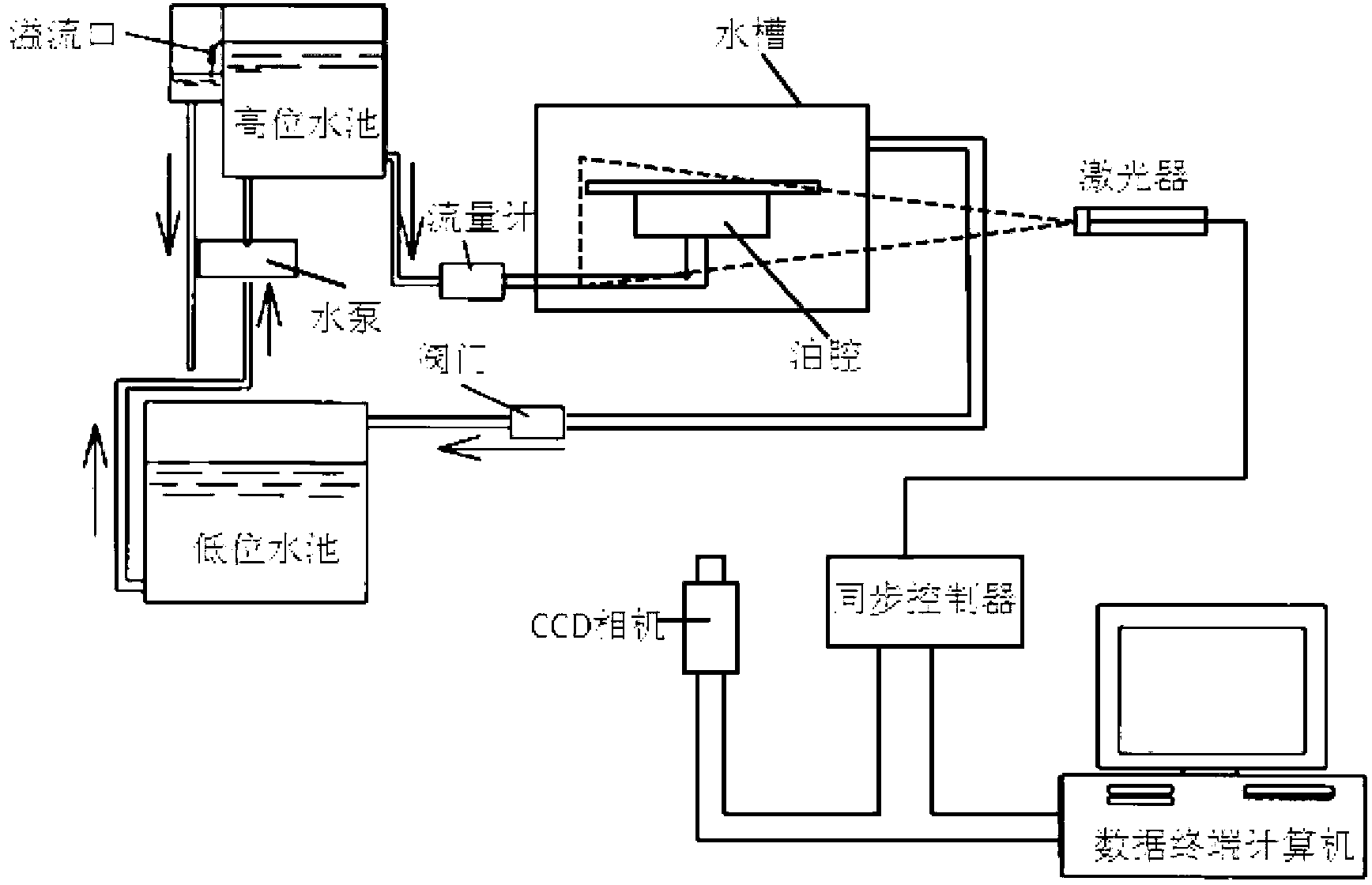
[0028] 1. According to image 3 As shown in the figure, assemble and connect the relevant devices, and place the oil chamber in the water tank. Adjust the positions of the laser, CCD camera and oil cavity so that the camera can clearly capture the relevant areas.

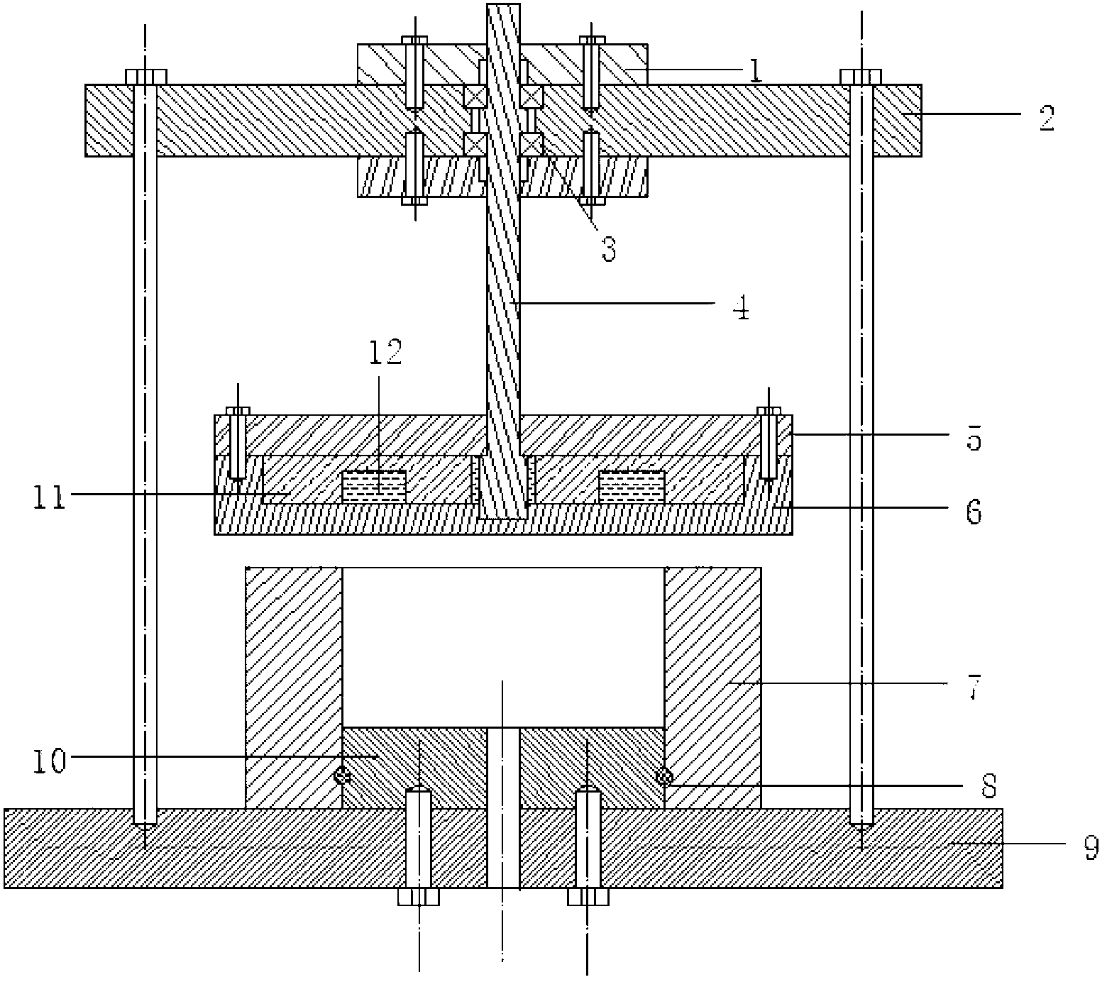
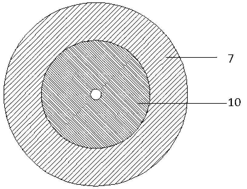
[0029] The oil chamber includes a base boss 10 , an annular side wall 7 and a bearing platform 6 . The base boss 10 is fixed on the base 9 by bolts, and a pipe is embedded in a through hole in the center of the two as the inlet pipe of the oil chamber. The annular side wall 7 is sleeved on the periphery of the base boss 10 and sealed by a sealing ring 8 .

[0030] There are supporting platform 2, main shaft 4 and supporting platform 6 above the annular side wall 7 from top to bottom; ; The main shaft 4 is connected with an external motor; There is no contact between the bearing platform 6 and the annular side wall 7 to form a gap;

[0031]The carrying platform 6 is fixed on the casing 5 by bolts, and the heatin...


PUM


Abstract

A flow field observing device for an oil cavity comprises the oil cavity, a loop system and a PIV (particle image velocimetry) system. The oil cavity comprises a base boss, an annular side wall and a carrier. The base boss is fixed on a base through bolts, and both the base boss and the base are provided with through holes with pipes embedded to be as inlet pipes of the oil cavity. The annular side wall is sleeved on the periphery of the base boss, a support platform, a spindle and the carrier are sequentially arranged above the annular side wall from top to bottom, the support platform is fixed on the base through the bolts, and the spindle and the support platform are connected through bearings and bearing end caps. The spindle is externally connected with a motor, the spindle and the carrier are fixedly connected, and the carrier and the annular side wall do not contact to form a gap. The loop system comprises a high-level water tank, a low-level water tank, a water pump, a valve and a water tank. The PIV system comprises a laser, a CCD (charge coupled device) camera, a synchronous controller and a computer. The flow field observing device is simple and convenient, results are accurate and reliable, variations of the flow field structure in the oil cavity under different conditions can be researched, all results are rich, and various states of the flow field can be observed.

Description

technical field [0001] The invention relates to a device and an operation method capable of conducting experiments to observe the internal flow field structure of an oil cavity. Background technique [0002] In a fluid power system (such as hydraulic transmission, hydraulic hydrodynamic lubrication, and dynamic and static pressure support systems, etc.), there must be a certain gap (or gap) between the parts with relative motion, and the flow of viscous fluid and liquid film in the micro-scale gap The dynamic characteristics of the system have a wide impact on the overall performance and operational reliability of the system. With the development of science and technology in modern society, aerospace technology, shipbuilding industry, automobile industry and high-precision instrument application fields have made great progress, and more and more requirements have been put forward for the machining accuracy, size, bearing capacity and processing speed of machine tools. high ...

Claims


Application Information

Patent Timeline
Patent Type & Authority Applications(China)
IPC IPC(8): G01M10/00
Inventor 申峰陈从连刘赵淼
Owner BEIJING UNIV OF TECH
Why Eureka
Try Eureka