
A test system for testing rotor type energy recovery device

A technology of energy recovery device and test system, which is applied in the direction of measuring device, testing of machine/structural components, instruments, etc., can solve the problems of inconvenient testing, high cost, certain problems in accuracy and reliability, and achieve compact structure. , reliable use, comprehensive performance evaluation

Active Publication Date: 2016-08-03
NINGBO INST OF MATERIALS TECH & ENG CHINESE ACADEMY OF SCI
View PDF3 Cites 0 Cited by
  • Summary
  • Abstract
  • Description
  • Claims
  • Application Information

AI Technical Summary

Problems solved by technology

In practice, the performance of the energy recovery device can only be tested when the desalination system is running, so the test is inconvenient and expensive
Moreover, in the membrane seawater desalination system, not only the energy recovery device is included, but also the main equipment is the reverse osmosis reactor. Therefore, there are certain problems in the accuracy and reliability of the test.

Method used


Image

  • A test system for testing rotor type energy recovery device
  • A test system for testing rotor type energy recovery device
  • A test system for testing rotor type energy recovery device

Examples


Embodiment 1

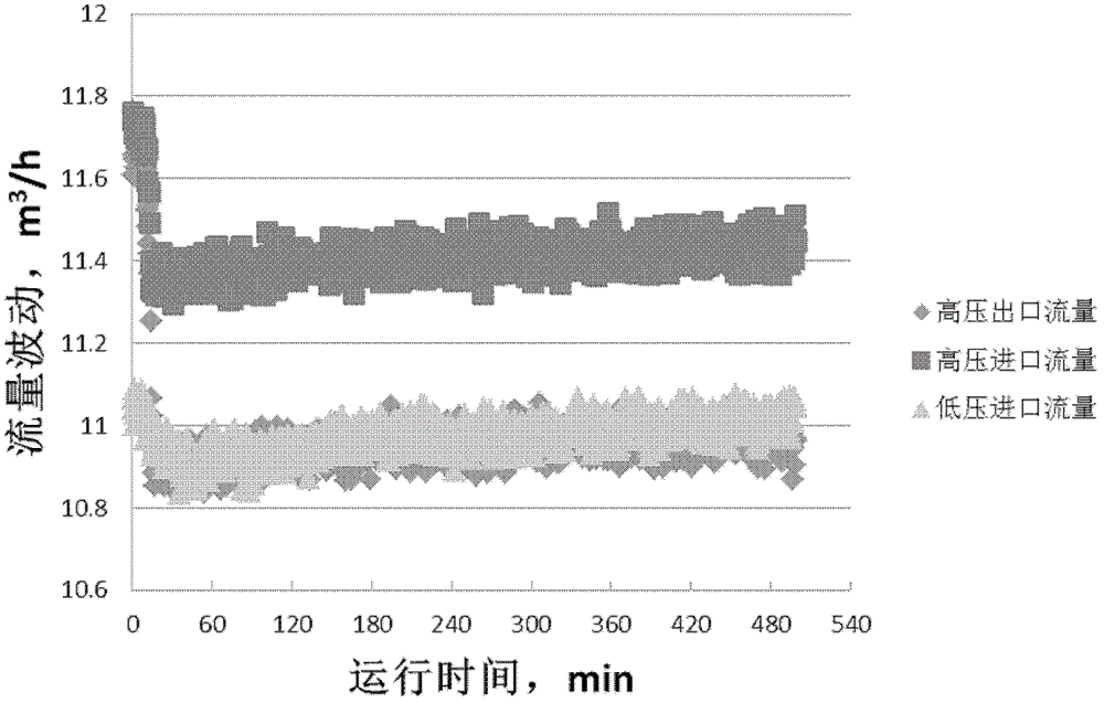
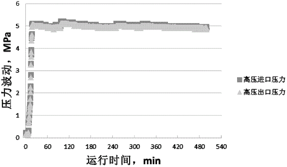
[0063] In this embodiment, the processing capacity is 10-20m 3 / h of the rotor energy recovery device 5 at a flow rate of 10m 3 / h, the performance test of the energy recovery device was carried out under the condition of operating pressure of 5.0MPa.

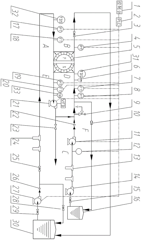
[0064] First, after the preparations for the test system are confirmed to be correct, start the water supply pump 15 to fill the high-pressure pipeline with water; open the exhaust valve 6 to empty the air in the high-pressure pipeline; then start the booster pump 22 to increase the rotor speed , and further exhaust through the exhaust valve 6;

[0065] Next, start the water supply pump 28 again, and adjust the water supply flow of the low-pressure pipeline to the required flow value by adjusting the opening and closing degree of the regulating valve 28 at the outlet of the pump;

[0066] Next, adjust the frequency converter frequency of the booster pump 22 to control the flow of concentrated brine in the high-pressure pipeli...

Embodiment 2

[0071] In this embodiment, the processing capacity is 20-30m 3 / h of the rotor energy recovery device 5 at a flow rate of 20m 3 / h, the performance test of the energy recovery device was carried out under the condition of operating pressure of 5.5MPa.

[0072] The operation steps of this embodiment are the same as those of Embodiment 1, so they will not be described in detail here.

[0073] After testing, the results show that the energy recovery efficiency of the energy recovery device reaches an average of 96%, and the lubrication flow rate is less than 0.6m 3 / h, the degree of mixing is less than 4%.

Embodiment 3

[0075] In this embodiment, the processing capacity is 30-40m 3 / h of the rotor energy recovery device 5 at a flow rate of 30m 3 / h, the performance test of the energy recovery device was carried out under the condition of operating pressure of 5.5MPa.


PUM


Abstract

The invention discloses a test system for testing a rotor type energy recycling device. The system is composed of the rotor type energy recycling device, a low-pressure pipeline part, a high-pressure pipeline part and a system control and data collection unit. The low-pressure pipeline part and the high-pressure pipeline part are connected with an inlet and an outlet of the energy recycling device, the system control and data collection unit controls the high-pressure pipeline part and the low-pressure pipeline part to conduct various device motions, collect corresponding information, and conduct corresponding analysis processing, and therefore various performance indexes such as the energy recycling efficiency, lubricating flow, inlet and outlet pressure dropping and system stability of the rotor type energy recycling device are obtained. The test system has the advantages of being compact in structure, reliable in use, flexible in operation, strong in adjustability and the like.

Description

technical field [0001] The invention relates to a seawater desalination system, in particular to a test system for testing a rotor-type energy recovery device in the seawater desalination system. Background technique [0002] At present, the working pressure of the reverse osmosis membrane in the reverse osmosis seawater desalination system is 5.0-8.0MPa, and the residual pressure of the concentrated brine discharged from the reverse osmosis membrane stack is as high as 4.0-6.0MPa. If calculated according to the usual 40% water production rate, about 60% of the concentrated brine residual pressure energy will be wasted, so recovering the concentrated brine residual pressure of the reverse osmosis membrane stack can greatly reduce the operating cost of seawater desalination and the cost of water production. As one of the main equipments of reverse osmosis seawater desalination system, energy recovery device can be divided into hydraulic turbine type and positive displacement ...

Claims


Application Information

Patent Timeline
Patent Type & Authority Patents(China)
IPC IPC(8): G01M99/00
Inventor 王蔚国苗鹤余洪良
Owner NINGBO INST OF MATERIALS TECH & ENG CHINESE ACADEMY OF SCI
Learn More