
Multi-way high-energy high-speed electromagnetic force impact intelligent control testing device and method

An intelligent control and test device technology, applied in the field of solid material impact, can solve the problems of insufficient intelligent control of triggering and data acquisition, inability to realize multi-directional force, insufficient impact acceleration, etc., to achieve controllability and adjustability, intelligent The effect of high degree of chemicalization, increasing the impact speed and impact energy

Inactive Publication Date: 2013-09-11
GUANGDONG UNIV OF TECH
View PDF5 Cites 45 Cited by
  • Summary
  • Abstract
  • Description
  • Claims
  • Application Information

AI Technical Summary

Problems solved by technology

Due to the high air pressure of the air pressure source required by this method, it is usually difficult to implement in civil laboratories.
[0005] 2. Free fall (drop) impact method
[0012] 3) The impact acceleration is not large enough;
[0013] 4) It can only give thrust in the horizontal or approximate horizontal direction, and cannot provide force in multiple directions;
[0014] 5) Insufficient intelligent control in terms of triggering and data acquisition
[0015] There is no test system that integrates multi-directional, high-energy, high-speed impact intelligent controllable (energy and speed adjustable)

Method used


Image

  • Multi-way high-energy high-speed electromagnetic force impact intelligent control testing device and method
  • Multi-way high-energy high-speed electromagnetic force impact intelligent control testing device and method
  • Multi-way high-energy high-speed electromagnetic force impact intelligent control testing device and method

Examples


Embodiment

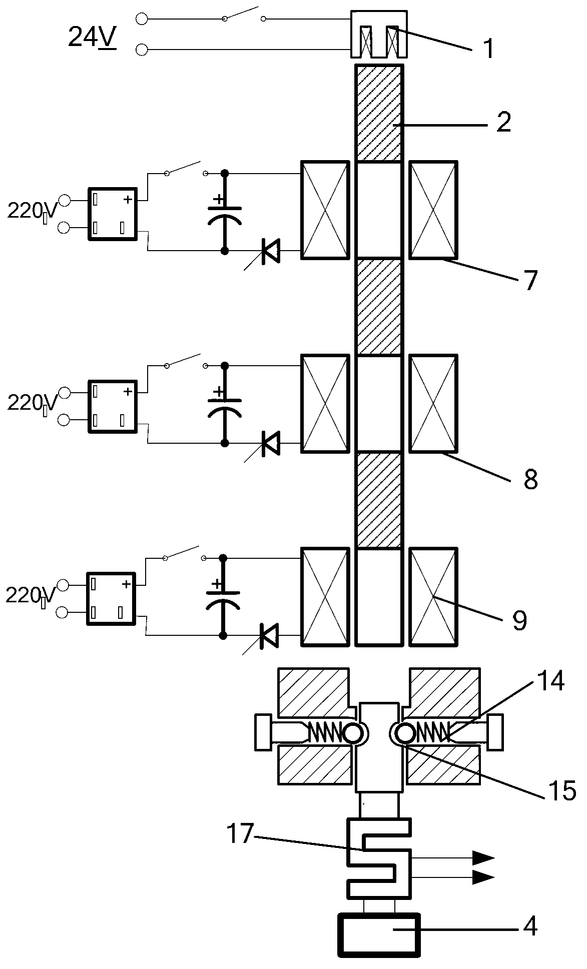
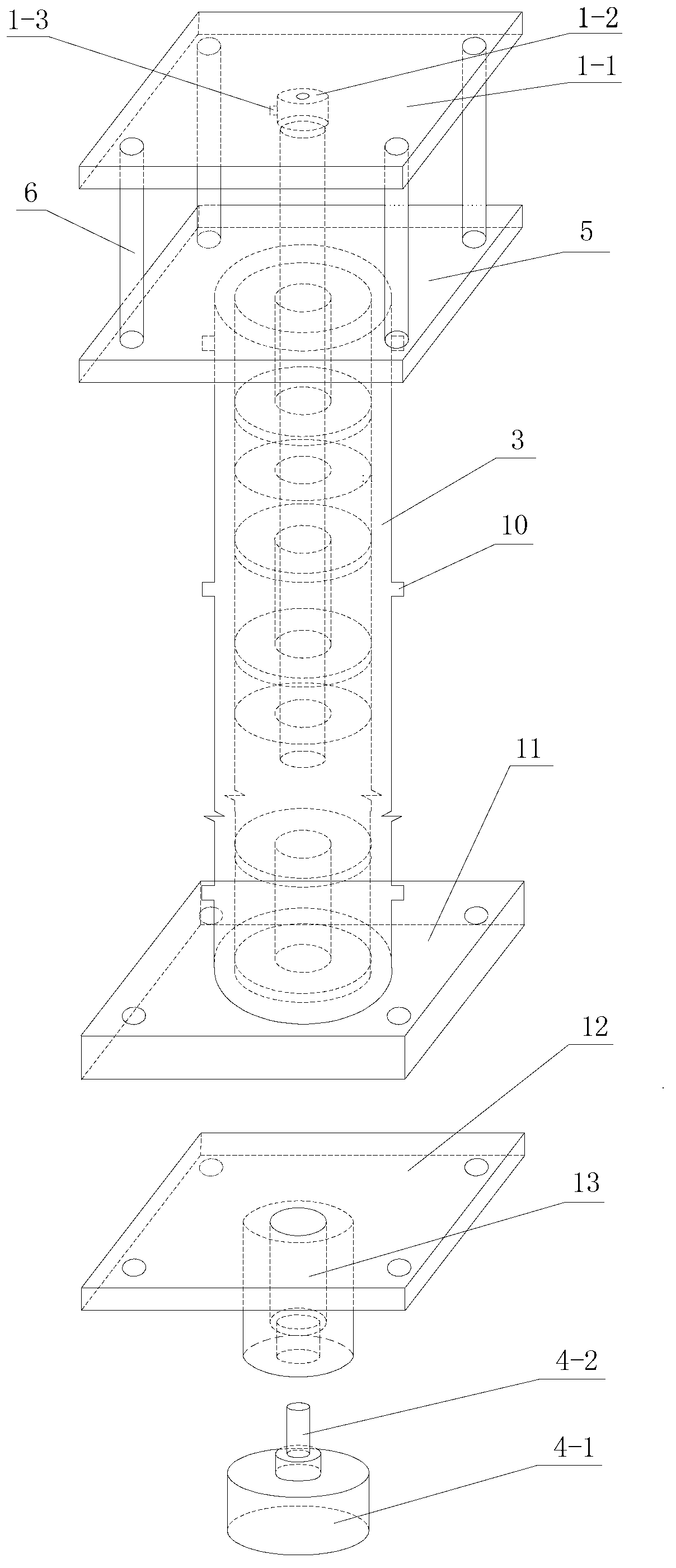
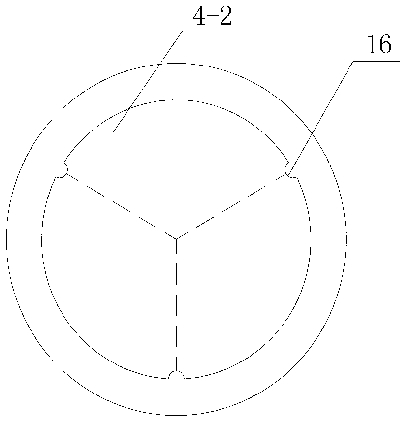
[0050] In this embodiment, a multi-directional high-energy high-speed electromagnetic force impact intelligent control test device is taken as an example where the device is placed in the vertical direction, as shown in figure 1 or figure 2 As shown, it includes an electromagnet assembly 1, a striking rod 2, an outer sleeve 3 and an impact hammer 4. The electromagnet assembly is arranged above the outer sleeve, the striking rod is arranged inside the outer sleeve, and the impact hammer is arranged below the outer sleeve. The outer periphery of the impact rod is provided with multi-stage electromagnetic acceleration coils, and the electromagnetic acceleration coils at each level are respectively externally connected to a circuit control system.

[0051] The electromagnet assembly 1 includes an electromagnet fixing plate 1-1 and a sucker-type electromagnet 1-2. The middle part of the electromagnet fixing plate is provided with a sucker-type electromagnet, and the sucker-type el...


PUM


Abstract

The invention discloses a multi-way high-energy high-speed electromagnetic force impact intelligent control testing device and method. The device comprises an electromagnet component, an impact rod, an outer sleeve, an electromagnetic acceleration coil group and an impact hammer, wherein the electromagnet component, the impact rod and the impact hammer are arranged above the outer sleeve, in the sleeve and below the sleeve, respectively; multi-stage electromagnetic acceleration coils arranged at the periphery of the impact rod are respectively and externally connected with a circuit control system. According to the method, acceleration is realized through sequential electromagnetic functions of the multi-stage electromagnetic acceleration coils in a moving process of the impact rod, and the impact energy and speed are increased and can be adjusted; the impact is set and limited in any direction through a base and the electromagnet component. According to the device and method, the electromagnetic stage acceleration impact rod is adopted, the impact speed and impact energy of the impact rod can be effectively increased and adjusted, the direction can be set according to the needs, the impact force is over 1000 times that of the weight of the impact hammer, the maximum times approximates to 3,000, a mains supply is used as a power source, and the device is well applied to a solid dielectric test in the field of civil engineering.

Description

technical field [0001] The invention relates to a solid material impact technology for civil engineering, in particular to a multi-directional high-energy high-speed electromagnetic force impact intelligent control test device and method. Background technique [0002] In the field of civil engineering, the mechanical responses of materials and structures under impact loads are significantly different from those under static loads. In engineering and other practical problems, impacts can cause serious damage. Impact involves a wide range of issues (for example, the mechanical response characteristics under impact loads are the basis for establishing dynamic constitutive relations, mechanical analysis and reasonable engineering design, and are also the basis for material models and material property data in various simulation technologies), Therefore, the physical and mechanical behavior test of materials and structures under impact load has become an indispensable technical m...

Claims


Application Information

Patent Timeline
IPC IPC(8): G01N3/317G01M7/08
Inventor 李彰明杨文龙
Owner GUANGDONG UNIV OF TECH
Learn More