Filter

A filter and resonator technology, applied in the field of filters, can solve the problems of small perturbation, small bandwidth, low filter Q value, etc., and achieve the effect of large perturbation and enhanced coupling effect.

Active Publication Date: 2013-09-11
KUANG CHI INST OF ADVANCED TECH
View PDF3 Cites 13 Cited by
  • Summary
  • Abstract
  • Description
  • Claims
  • Application Information

AI Technical Summary

Problems solved by technology

However, the disadvantage of the tuning screw is that the amount of perturbation is small, so that the coupling effect of the two degenerate modes is very small, resulting in small bandwidth and weak filtering function.
At the same time, the tuning screw will also cause the Q value of the filter to be greatly reduced

Method used


Image

  • Filter
  • Filter
  • Filter

Examples


Embodiment Construction

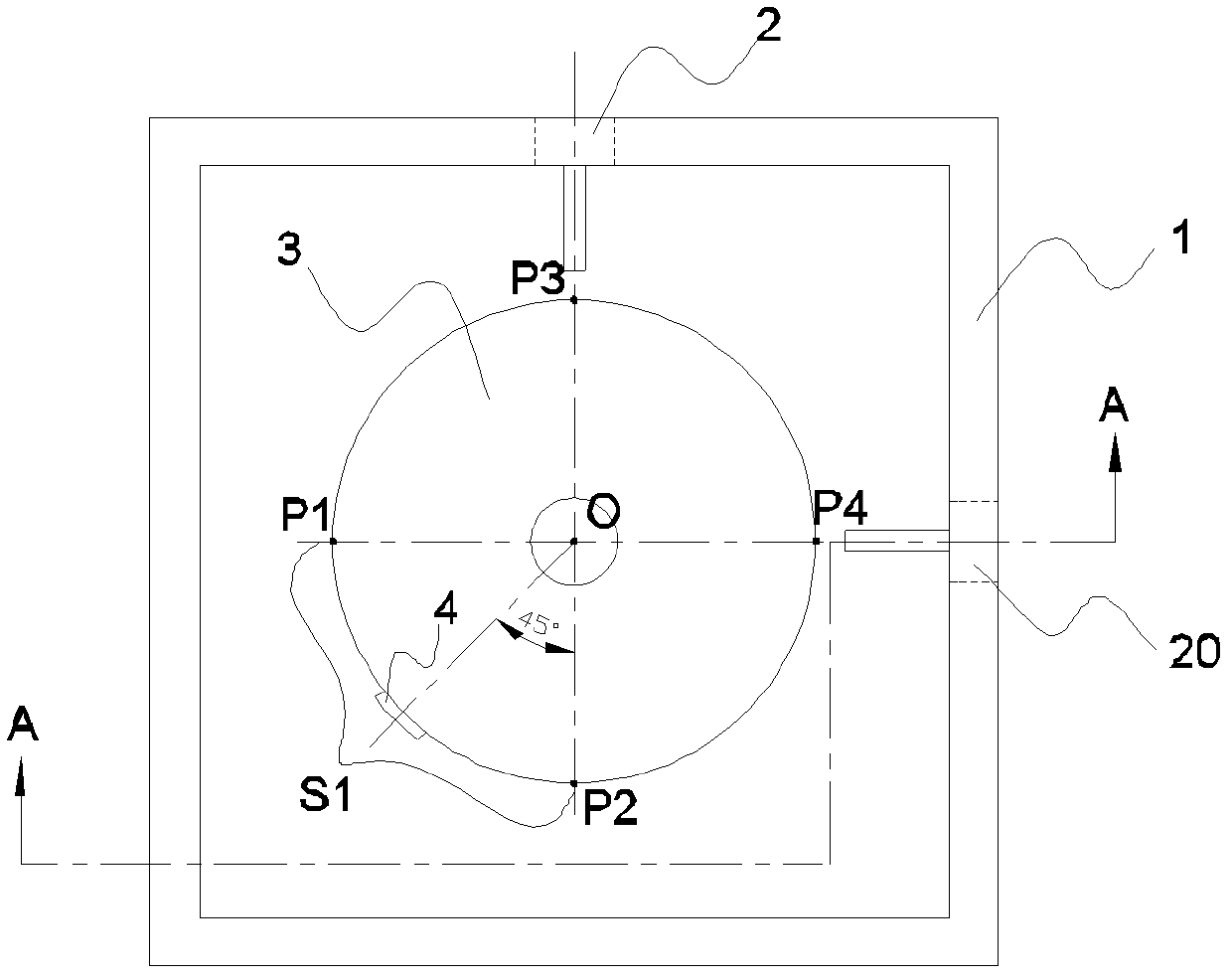
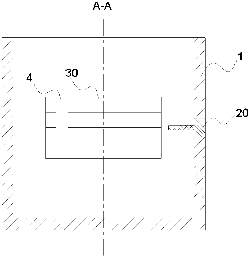
[0021] The present invention relates to a filter, the preferred embodiment is as figure 1 , figure 2 As shown, it includes a resonant cavity 1 , an input end 2 , an output end 20 , a resonator 3 and a metal sheet 4 .

[0022] Wherein, the resonant cavity 1 in this embodiment is in the shape of a square column with a square end face. The input end 2 and the output end 20 are respectively located in the middle of the two adjacent side walls of the resonant cavity 1, and point to the center of the resonant cavity 1 perpendicular to the side walls, that is, the central axes of the two are perpendicular to each other and both pass through the resonant cavity center of.

[0023] Preferably, the resonator 3 is located in the middle of the resonator 1, that is, the distance from the resonator 3 to the top and bottom surfaces of the resonator 1 is equal, and the distance from the sides of the resonator 3 to the side walls of the resonator 1 is equal. Of course, the harmonic oscilla...


PUM


Abstract

The invention relates to a filter comprising a resonant cavity, an input end, an output end and a harmonic oscillator arranged in the resonant cavity, wherein the input end and the output end are installed on the side wall of the resonant cavity and stretch into the resonant cavity, the input end and the output end are arranged in a mutually perpendicular mode, and metal pieces are attached to the surfaces, synchronously back on to the input end and the output end, of the harmonic oscillator. Due to the fact that the metal pieces are arranged, perturbation can be formed for two degenerate molds, and perturbation amount is large, therefore, the coupling effect of the two degenerate molds can be made to be enhanced, further, a certain bandwidth is formed, and a filtering effect is achieved.

Description

technical field [0001] The present invention relates to radio frequency devices, and more particularly to a filter. Background technique [0002] Filters are key components in electronic systems and are used to perform frequency selection functions. Commonly used filters include dielectric filters, cavity filters, lumped filters, etc. Dielectric filters are widely used because of their high Q value (quality factor value). The dielectric filter refers to a filter composed of a medium with high dielectric constant and low loss in a resonant cavity made of metal. The medium is mainly composed of ceramic materials. [0003] Generally, a single resonant cavity can realize one mode, but a multimode filter needs to use multiple cavities, resulting in a relatively large volume. To realize the miniaturization of the filter, it is necessary to realize the multimode function in a single cavity. The known single-cavity multi-mode technology is to introduce mutually perpendicular inpu...

Claims


Application Information

Patent Timeline
Patent Type & Authority Applications(China)
IPC IPC(8): H01P1/20H01P1/207
Inventor 刘若鹏徐冠雄刘京京陈悠杰
Owner KUANG CHI INST OF ADVANCED TECH
Why Eureka
Try Eureka