Small-sized piezoelectric resonator

Active Publication Date: 2006-11-21
ETA SA MFG HORLOGERE SUISSE
View PDF7 Cites 15 Cited by
  • Summary
  • Abstract
  • Description
  • Claims
  • Application Information

AI Technical Summary

Benefits of technology

[0010]The main goal of the invention is to provide a three arm resonator which enables to reduce the size of the resonator, and more particularly its length. For that purpose according to a first aspect of the invention, it concerns a piezoelectric resonator including a tuning fork shaped part with two parallel vibrating arms, connected to each other by a linking part, from which protrude a central arm located between both vibrating arms of the tuning fork shaped part, the vibrating arms carrying first electrodes to make them vibrate, these electrodes being

Problems solved by technology

One of these problems is that the dimensional and functional features of the conventional tuning fork resonators are optimised for mounting them in metallic cases and not in ceramic cases.
For example, the ratio between their length and their width is ill suited to the manufacture of such cases, in particular when the cases are of the SMD (Surface Mounting Device) type, i.e. meant to be automatically mounted on hole-free printed circuit boards.
Because of this, a conventional tuning fork resonator and its connection to the case do not have very good resistance to shocks.
Further conventional tuning fork resonators are liable to tip towards the bottom of the case when it is fixed onto a step of the case.
Furthermore, since the thermal expansion coefficients of ceramic material and quartz are different enough to create mechanic

Method used


Image

  • Small-sized piezoelectric resonator
  • Small-sized piezoelectric resonator
  • Small-sized piezoelectric resonator

Examples


first embodiment

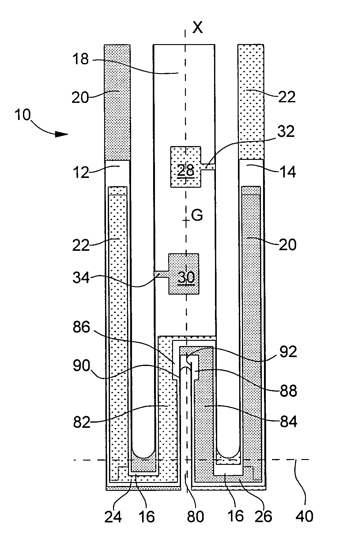
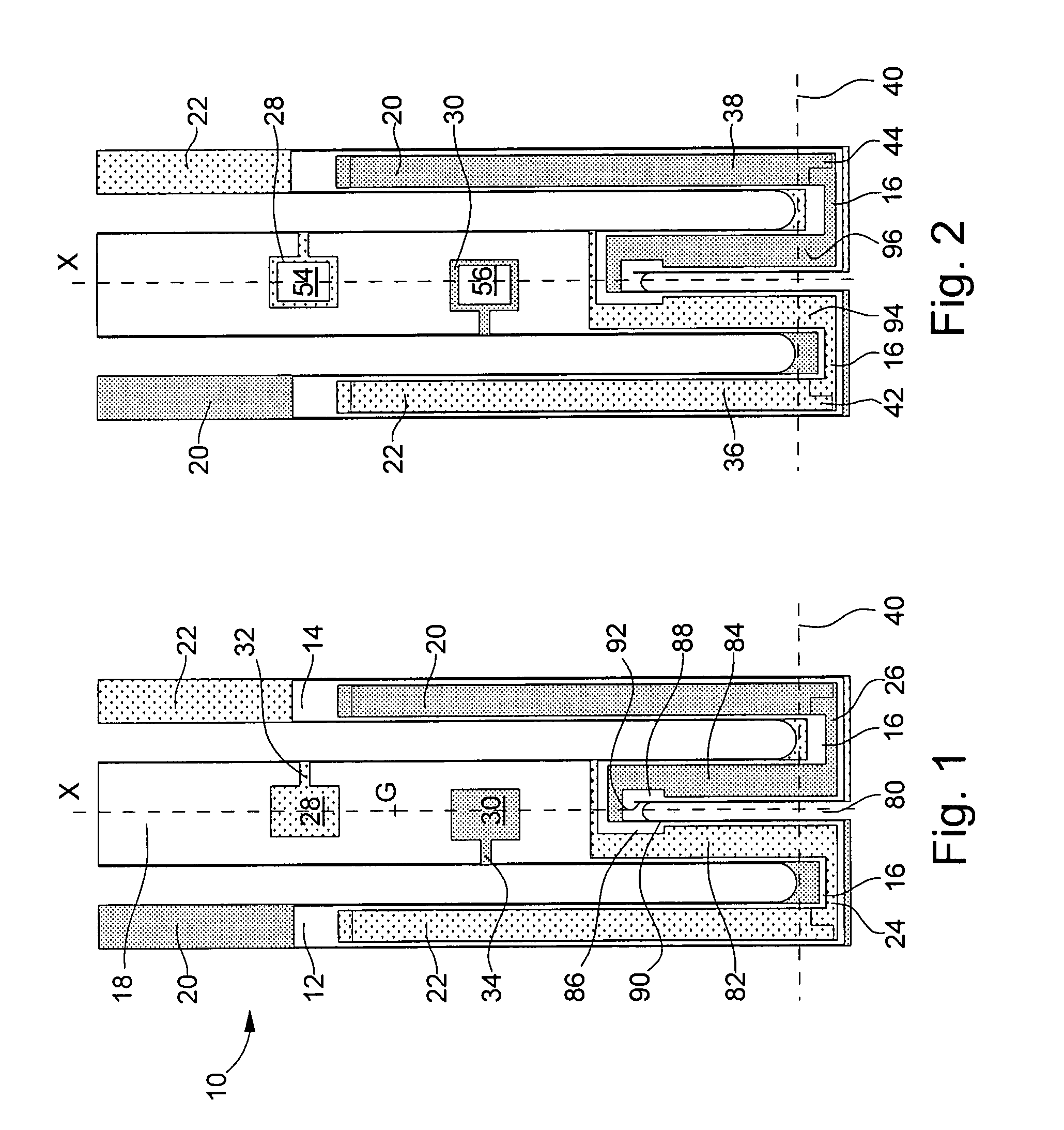
[0021]In the first embodiment shown in relation with FIG. 1, the resonator according to the invention, designated by the reference numeral 10, includes a tuning fork shaped part with two vibrating arms 12 and 14 joined by a linking part 16 to which a central arm 18, located between arms 12 and 14 and parallel thereto, is attached, the whole assembly being made in a single piece and of quartz.

[0022]As shown by FIG. 1, vibrating arms 12 and 14 carry two groups of electrodes 20 and 22, which are connected to each other by conductive paths respectively 24 and 26, carried by linking part 16 of the tuning fork shaped part. As they are shown in the drawing, these electrodes and conductive paths are disposed to make arms 12 and 14 vibrate in flexure mode, but they could have a different configuration to make the arms vibrate in the same mode or another mode (torsion, shear, etc.). Returning to central arm 18, FIG. 1a shows that it carries on its back face two conductive connection pads 28 a...

second embodiment

[0025]FIG. 2 shows a second embodiment which differs from the first one in that in order to reduce consumption of energy by producing an excitation electrical field which is more homogeneous and locally more intense and for which vibration loss at the arms is low even when the size of the vibrating piece is miniaturized, at least one groove 36, 38 is formed on at least one of a front side and a rear side of each vibrating arm, respectively 12, 14. It will be appreciated that the depth of these grooves is preferably between 30% and 50% of the thickness of the corresponding vibrating arm in the depth direction and advantageously between 40% and 50%. It is to be noted that this ratio may be applicable to all forthcoming embodiments with grooves. Use of such grooves on the vibrating arms furnishes precise performances even when the device is miniaturized. As alternatives only one groove may be provided either on the front or the rear side of each vibrating arm, or two grooves may be pro...

third embodiment

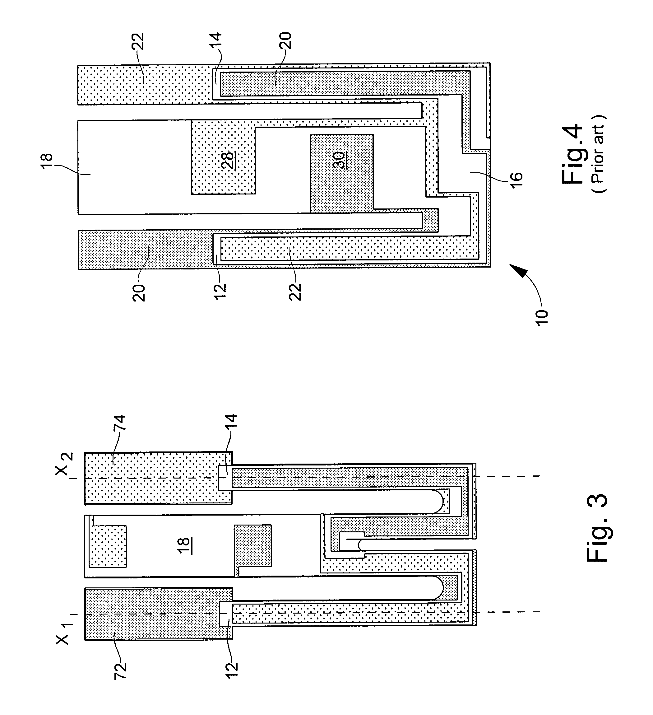
[0029]In the third embodiment shown in relation with FIG. 3, the resonator differs from the first one in that each vibrating arm 12, respectively 14, ends in a flipper 72, respectively 74. Preferably, these flippers 72 and 74 have a symmetrical rectangular shape with respect to the longitudinal axis (X1, X2) of corresponding vibrating arm 12, 14, the flipper width being approximately twice as that of vibrating arm. But in counterpart, it will appreciated that the flipper length can be deduced from the overall length of the vibrating arm without modifying the resonator properties, and that the length of central arm 18 is reduced accordingly in order not to extend beyond vibrating arms 12 and 14. Therefore the resonator length may be reduced accordingly.

[0030]It will be appreciated that preferably for further improving the shock resistance of the resonators according to any of the above presented embodiments, the cut out portions where vibrating arms 12, 14 or slot 80 are linked to li...


PUM


Abstract

The piezoelectric resonator according to the invention includes a tuning fork shaped part with two parallel vibrating arms, connected to each other by a linking part, from which protrude a central arm located between both vibrating arms of the tuning fork shaped part, the vibrating arms carrying first electrodes to make them vibrate, these electrodes being connected to connection elements carried by the central arm, wherein a slot has been cut within the linking part opposite to the central arm and wherein second electrodes have been arranged along said slot.

Description

FIELD OF INVENTION[0001]The present invention concerns piezoelectric resonators and more particularly resonators of small dimensions which are most often used for making frequency generators in particular for portable electronic equipment, in numerous fields such as horology, information technology, telecommunications and the medical field.BACKGROUND OF THE INVENTION[0002]Such a resonator of small dimensions has been disclosed in the prior art document U.S. Pat. No. 6,700,313 filed in the name of the name Assignee, which is enclosed herewith by way of reference. Resonator 10 represented on FIG. 4, which is intended to be mounted in a case, includes a tuning fork shaped part with two parallel arms 12, 14 connected to each other by a linking part 16 and carrying electrodes 20, 22 to make them vibrate, these electrodes being connected to connecting pads 28, 30 intended to be electrically connected to the exterior of the case. Resonator 10 also includes a central arm 18 attached to link...

Claims


Application Information

Patent Timeline
IPC IPC(8): H01L41/08
CPCH03H9/21
Inventor DALLA PIAZZA, SILVIOSTUDER, BRUNOLUETHI, THOMAS
Owner ETA SA MFG HORLOGERE SUISSE
Why Eureka
Try Eureka