Method for achieving phased-array antenna gain self-adaptation control

An adaptive control and phased array antenna technology, applied in the field of measurement and control communication, can solve the problems of phased array antenna beam narrow, waste of system energy, power consumption of antenna equipment, etc., to achieve small output margin and high equipment working efficiency , The effect of reducing power consumption

Inactive Publication Date: 2013-09-11
10TH RES INST OF CETC
View PDF4 Cites 10 Cited by
  • Summary
  • Abstract
  • Description
  • Claims
  • Application Information

AI Technical Summary

Problems solved by technology

With the development of measurement and control communication technology, the demand for high-speed data transmission is urgent, and high-speed data transmission requires the system antenna to have a high equivalent radiated power EIRP value. The EIRP value of a phased array antenna is the sum of the antenna gain and the output power of all array elements. The beam of the phased array antenna with high EIRP value is narrow. When capturing the target signal, it is difficult to align the narrow antenna beam with the target, and target guidance is required. In severe cases, there is enough margin for the antenna EIRP value. In this way, the phased array antenna works in the full power output state all the time during the actual system work process, which causes the antenna equipment to consume a lot of power and waste a lot of system energy. At the same time, it must use It is specially designed for the heat dissipation measures of the phased array antenna. For the aircraft platform with tight energy demand, this design mode is quite unfavorable.

Method used


Image

  • Method for achieving phased-array antenna gain self-adaptation control

Examples


Embodiment Construction

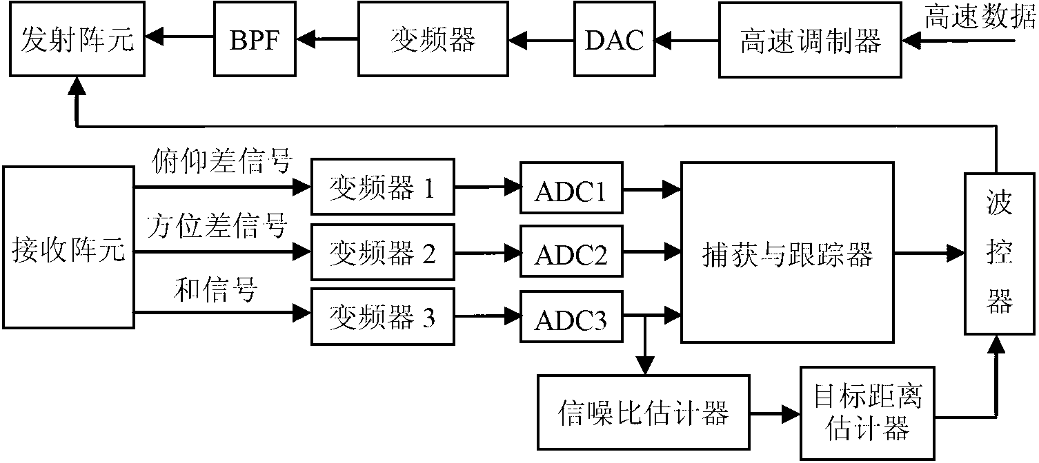
[0010] Refer to figure 1 . In the following embodiments, the method for implementing adaptive control of phased array antenna gain includes forming a pitch difference signal, an azimuth difference signal, and a sum signal after receiving the target signal by the phased array receiving element, and sending them to the inverter 1, respectively Frequency converter 2 and frequency converter 3 perform down-conversion processing, and then respectively send to analog-to-digital converter ADC1, analog-to-digital converter ADC2, and analog-to-digital converter ADC3 for sampling, and then to capture and tracker for signal detection. After the capture and tracker receives the pitch difference signal, the azimuth difference signal and the sum signal formed by the receiving antenna array element, by extracting the signal phase, it can obtain the azimuth and pitch angle information of the target relative to the phased array receiving antenna in real time, which is a wave controller Control t...


PUM


Abstract

The invention provides a method for achieving phased-array antenna gain self-adaptation control. The method can keep small output allowances, and improves the working efficiency of equipment. According to the technical scheme, the method comprises the steps that a phased-array receiving array element receives pitching difference signals, azimuth difference signals and signals, the pitching difference signals, the azimuth difference signals and the signals are formed by target signals, corresponding frequency converters carry out down frequency conversion processing on the pitching difference signals, the azimuth difference signals and the signals respectively, the pitching difference signals, the azimuth difference signals and the signals are then sampled through analog-to-digital converters correspondingly connected and are sent to a trapping and tracking device, signal trapping and signal tracking are carried out, an azimuth angle and an pitching angle are output to a wave controller, signal-to-noise-ratio detection and target distance evaluation are carried out by the wave controller and a first signal separating path, the ETRP value of an emitting antenna is calculated according to a distance evaluating value, and the quantity combination of emitting antenna array elements and beam pointing control are achieved through the wave controller; high-speed data input in a high-speed modulator are modulated on an emitting signal carrier wave and are sent to DAC to be reconstructed and processed, and the formation of space beams pointing a target direction is achieved.

Description

Technical field [0001] The invention relates to a phased array system measurement and control system in the field of measurement and control communication, and provides an implementation method of antenna gain adaptive control to realize the optimal EIRP value output of the system under the condition of determining the transmission rate. Background technique [0002] The phased array antenna uses a certain number of radiating array elements, and a wave controller is used to control the phase of the radiation signal of each array element, so that the combined beam of the array element can point to a certain spatial direction. The phased array antenna has the characteristics of high gain and rapid beam direction scanning. The gain of the phased array antenna increases with the increase of the number of its elements, and the antenna beam width narrows with the increase of the number of elements. With the development of measurement and control communication technology, the demand for...

Claims


Application Information

Patent Timeline
Patent Type & Authority Applications(China)
IPC IPC(8): H01Q3/24H01Q21/00
Inventor 万永伦
Owner 10TH RES INST OF CETC
Why Eureka
Try Eureka