
Novel video cable

A video cable, a new type of technology, applied in the field of communication, can solve the problems of the new video cable falling off, the shielding effect is not good, the wire core cannot withstand voltage and high temperature, etc., to achieve excellent anti-interference characteristics, improve transmission effect, and enhance anti-interference ability. Effect

Inactive Publication Date: 2013-09-11
周国清
View PDF1 Cites 0 Cited by
  • Summary
  • Abstract
  • Description
  • Claims
  • Application Information

AI Technical Summary

Problems solved by technology

[0002] As the name suggests, the new type of video cable is used to transmit video signals. It is a coaxial cable used to transmit video baseband analog signals. An impedance, often used to output video signals, such as the Chinese patent application No. 201220003933.2 application document discloses a double-layer coaxial new video line, including a three-layer structure, wherein the innermost is a conductor, and the conductor is covered with extruded plastic The formed core wire material layer is covered with an extruded insulating material layer; the core wire material layer and the insulating material layer are both made of PE (polyethylene), and the present invention is formed by extruding outside the conductor A layer of PE core wire material layer, extruded outside the core wire material layer to form a PE insulating material layer, thus the invention has the following advantages: First, the conductor and the core wire material layer have stronger adhesion, and the conductor is not easy to peel off, making the video signal more Stable; second, double-layer extrusion can more effectively control the generation of air bubbles, which can also make the video signal more stable, but it does not solve the problem that the shielding effect is not good, the new video cable is easy to fall off from the plug, and the core cannot withstand pressure and high temperature And other issues

Method used


Image

  • Novel video cable

Examples


Embodiment Construction

[0011] The present invention will be described in further detail below in conjunction with the accompanying drawings and specific embodiments.

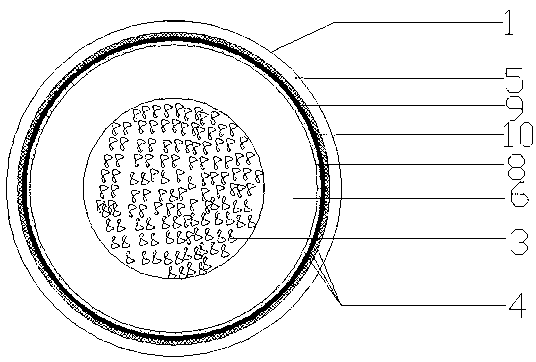
[0012] see figure 1 , a new type of video cable, including a line body 1 and a plug 2, the line body 1 includes a core 3, a shielding layer 4, an outer sheath 5, an insulating layer 6 is provided outside the core 3, and the line body 1 and the plug 2 are connected with a reinforcing head 7, the wire core 3 is Teflon and copper wire strands, the shielding layer 4 includes a thin rubber layer 8 and a copper-clad aluminum-magnesium wire braided mesh 9, the The thin rubber layer 8 is connected to the insulating layer 6, and the thin rubber layer 8 is provided with a cotton yarn layer 10, and the cotton yarn layer 10 is connected to the outer sheath 5 through the copper-clad aluminum-magnesium wire braided mesh 9, and is connected to the line body and the plug. There is a reinforced head to increase the firmness of the connection between...


PUM


Abstract

The invention relates to the field of communication and discloses a novel video cable which comprises a cable body and a plug. The cable body comprises a cable core, a shielding layer and an outer sheath, an insulating layer is arranged outside the cable core, a reinforcing head is arranged at the joint of the cable body and the plug, the cable core is a stranded object of teflon and copper wires, the shielding layer comprises a thin rubber layer and a copper-coated aluminum and magnesium wire woven mesh, the thin rubber layer is connected with the insulating layer, and a cotton yarn layer is arranged outside the thin rubber layer and connected with the outer sheath through the copper-coated aluminum and magnesium wire woven mesh. By the above mode, various functions of the novel video cable can be optimized, connection firmness of the cable body and the plug can be improved, and wearing and shedding can be prevented; the teflon is tiny in outer diameter, so that saving of raw materials, compression resistance and high temperature resistance can be realized; the thin rubber layer can improve ductility and tenacity, the cotton yarn layer can improve flexibility, and the copper-coated aluminum and magnesium wire woven mesh can improve resistance to low-frequency super-strong electromagnetic interference.

Description

technical field [0001] The invention relates to the field of communication, in particular to a novel video cable. Background technique [0002] As the name suggests, the new video cable is used to transmit video signals. It is a coaxial cable used to transmit video baseband analog signals. It generally has two impedances of 75 ohms and 50 ohms. It is often used to output video signals. For example, the Chinese patent application number is The application document of 201220003933.2 discloses a new type of double-layer coaxial video cable, which includes a three-layer structure, the innermost of which is a conductor, and the outside of the conductor is covered with an extruded core wire layer, and the outside of the core wire layer is covered with Extruded insulating material layer; both the core wire material layer and the insulating material layer are made of PE (polyethylene). The invention has the following advantages by forming a PE insulating material layer: first, the ...

Claims


Application Information

Patent Timeline
Patent Type & Authority Applications(China)
IPC IPC(8): H01R13/58H01R13/56H01B7/17H01B7/18H01B11/20
Inventor 周国清
Owner 周国清
Learn More