
Overvoltage protection device and method for alternating current side of voltage source converter high voltage direct current transmission system

A technology of voltage protection and flexible direct current, which is applied to emergency protection circuit devices, emergency protection circuit devices, and circuit devices for limiting overcurrent/overvoltage. To avoid problems such as uncontrollable communication, to achieve the effect of ensuring safe and stable operation, reducing insulation costs, and quickly protecting the valve body

Active Publication Date: 2013-09-11
STATE GRID CORP OF CHINA +1
View PDF3 Cites 26 Cited by
  • Summary
  • Abstract
  • Description
  • Claims
  • Application Information

AI Technical Summary

Problems solved by technology

In this protection method, the gapless MOV is usually connected in parallel at both ends of the power semiconductor valve 9, and the voltage and current nonlinear characteristics of the MOV are used to dissipate the energy that may generate overvoltage through the MOV, so that the protected equipment is protected from the impact of overvoltage , but this method has defects such as difficulty in setting action parameters, excessive energy stress, and uncontrollable conduction.
However, other traditional line protection devices such as bypass thyristor switches have disadvantages such as complex structure, slow action time, and low ability to withstand overcurrent.

Method used


Image

  • Overvoltage protection device and method for alternating current side of voltage source converter high voltage direct current transmission system

Examples


Embodiment Construction

[0035] The specific implementation manners of the present invention will be further described in detail with examples in conjunction with the accompanying drawings.

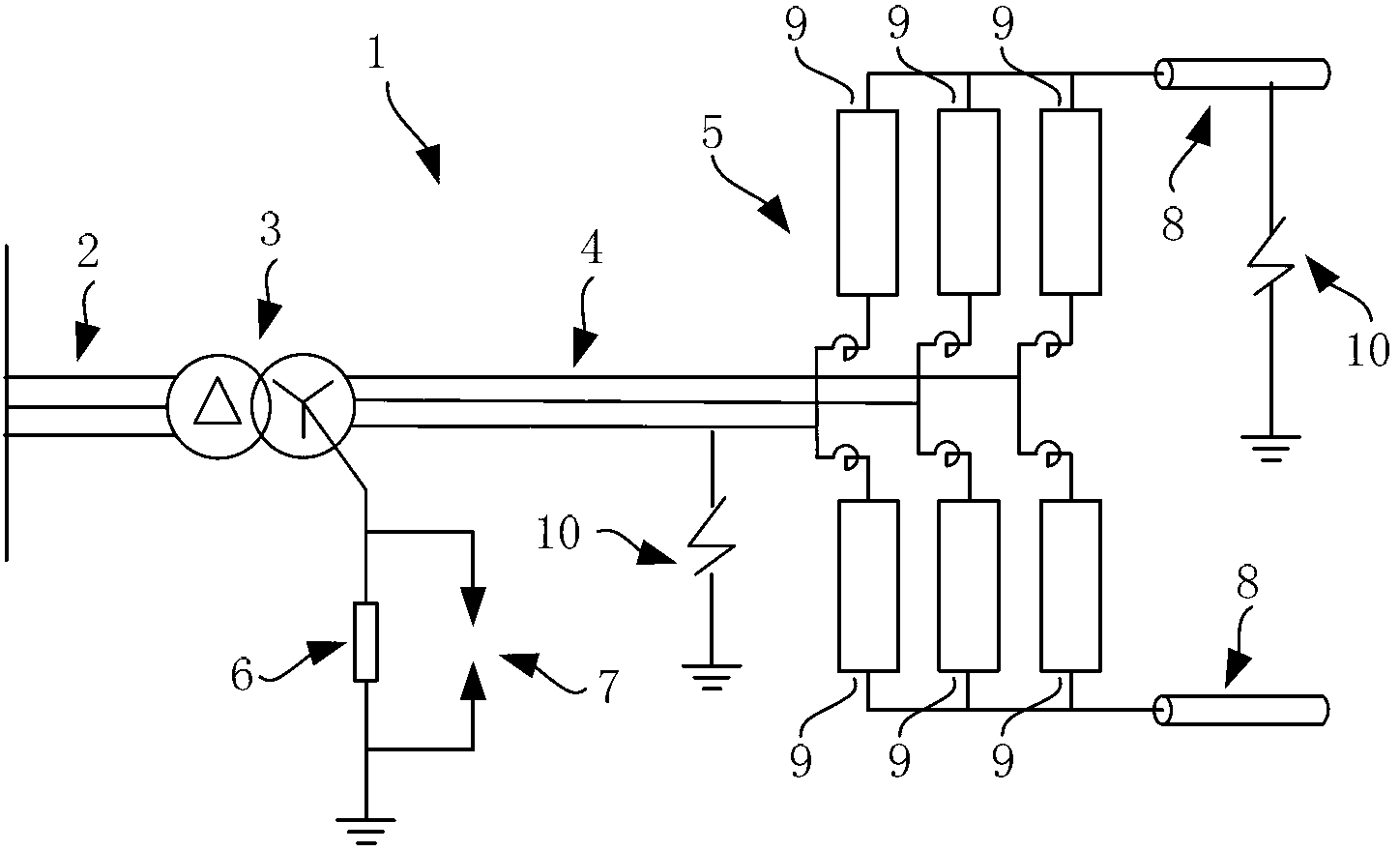
[0036] The overvoltage protection device for the AC line I and the converter valve of the flexible direct current transmission system provided by the present invention is as follows: figure 1 As shown, the protection device includes a converter valve 5 switching between the AC line I and the DC line 8, and a converter transformer 3 is provided between the AC line I and the AC line II, and the converter transformer 3 is connected to the AC line I. The valve side is connected in star form, and its neutral point is grounded through the grounding resistor 6; the converter transformer 3 is connected in delta or star form on the AC line II grid side.

[0037] The converter valve 5 is a three-phase six-leg structure; each bridge arm is composed of a converter valve body 9; the converter valve body 9 is realized by semic...


PUM


Abstract

The invention relates to an overvoltage protection device and method for the alternating current side of a voltage source converter high voltage direct current transmission system. The overvoltage protective device is connected to two ends of a ground resistor of the converter transformer valve side in parallel and used for acting to lead failure current away, restraining the level of overvoltage of an alternating current circuit I (4) and protecting a converter valve body (9) when overvoltage of a direct current circuit (8) exists due to a fault of the alternating current circuit I (4) or a fault of the direct current circuit (8) or a valve base controller detects the phenomenon that the alternating current circuit I (4) breaks down. The protective device is rapid in action, strong in through-flow capacity, large in absorbed energy, and capable of rapidly protecting the valve body. A control protective device with a complicated structure and complicated functions is not needed. The overvoltage protective device is simple in structure, low in cost and easy to implement, reduces the cost of the alternating current and insulation cost of a converter valve, guarantees safety of the alternating current circuit and the converter valve, improves fault-resistance ability of a converter station, and guarantees safe and stable operation of the voltage source converter high voltage direct current transmission system.

Description

technical field [0001] The invention relates to the field of flexible direct current transmission systems, in particular to an overvoltage protection device and protection method for an AC side of a flexible direct current transmission system. Background technique [0002] Flexible direct current transmission is a new type of high voltage direct current transmission technology, which converts traditional alternating current into direct current at power sources such as hydropower plants or thermal power plants through voltage source converters, and transmits power to to the remote load. Compared with traditional HVDC transmission, it has the advantages of strong controllability, easy power flow reversal, and no need for reactive power compensation. [0003] The flexible DC transmission system consists of three parts, including two converter stations located at the power source and the load, and a DC cable or overhead line connecting the two stations. The core equipment is th...

Claims


Application Information

Patent Timeline
Patent Type & Authority Applications(China)
IPC IPC(8): H02H9/06
CPCH02H7/1252H02H9/06
Inventor 荆平邱宇峰周飞陆振纲
Owner STATE GRID CORP OF CHINA
Learn More