
Device for controlling temperature of an optical element

A technology of optical components and controllers, applied in the field of temperature devices, can solve problems such as thermal instability of the system, and achieve the effects of avoiding interference, good control, and preventing thermal drift effects.

Active Publication Date: 2013-09-11
CARL ZEISS SMT GMBH
View PDF8 Cites 9 Cited by
  • Summary
  • Abstract
  • Description
  • Claims
  • Application Information

AI Technical Summary

Problems solved by technology

Temperature variations of the heat sink cause thermal instability of the entire system due to disturbed thermal balance

Method used


Image

  • Device for controlling temperature of an optical element
  • Device for controlling temperature of an optical element
  • Device for controlling temperature of an optical element

Examples


Embodiment Construction

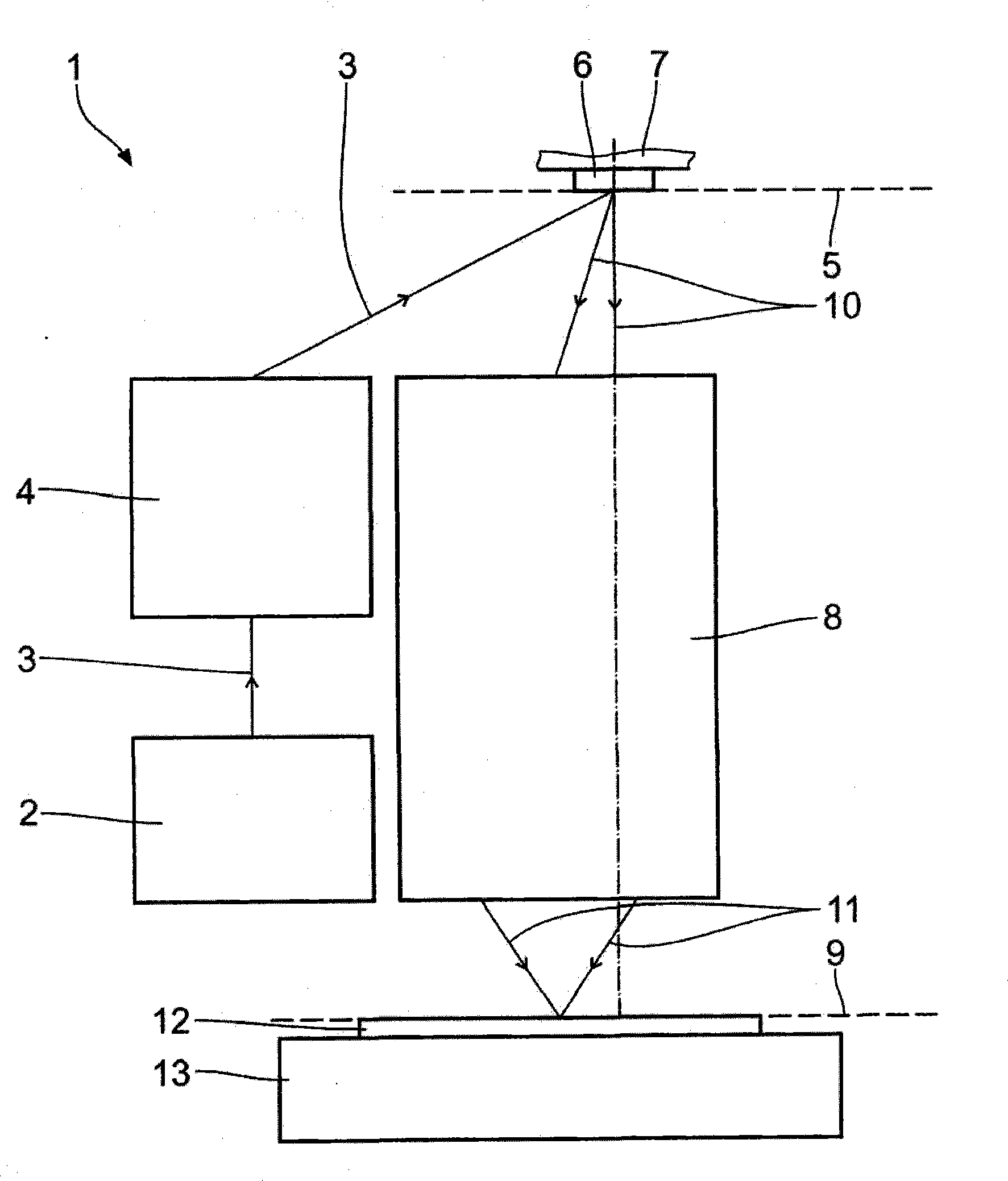
[0075] figure 1 An outline part of a microlithography tool 1 for producing microstructured components such as semiconductor microchips is schematically shown.

[0076] The microlithography tool 1 has an illumination source 2 emitting an illumination beam 3 . figure 1 In , only the chief ray of the illumination beam 3 is shown. The illumination source 2 is, for example, an extreme ultraviolet (EUV) source emitting radiation with a wavelength between 5 nm and 30 nm. Advantageously, the illumination source 2 is a plasma EUV source.

[0077] After being emitted from the illumination light source 2 , with the aid of the illumination optics 4 , the illumination beam 3 is formed and guided. The illumination light source 2 and the illumination optics 4 are part of the illumination system of the microlithography tool 1 . The illumination optical system 4 includes several figure 1 Optical mirrors not shown. The illumination optics 4 serve to provide specific illumination of the ob...


PUM


Abstract

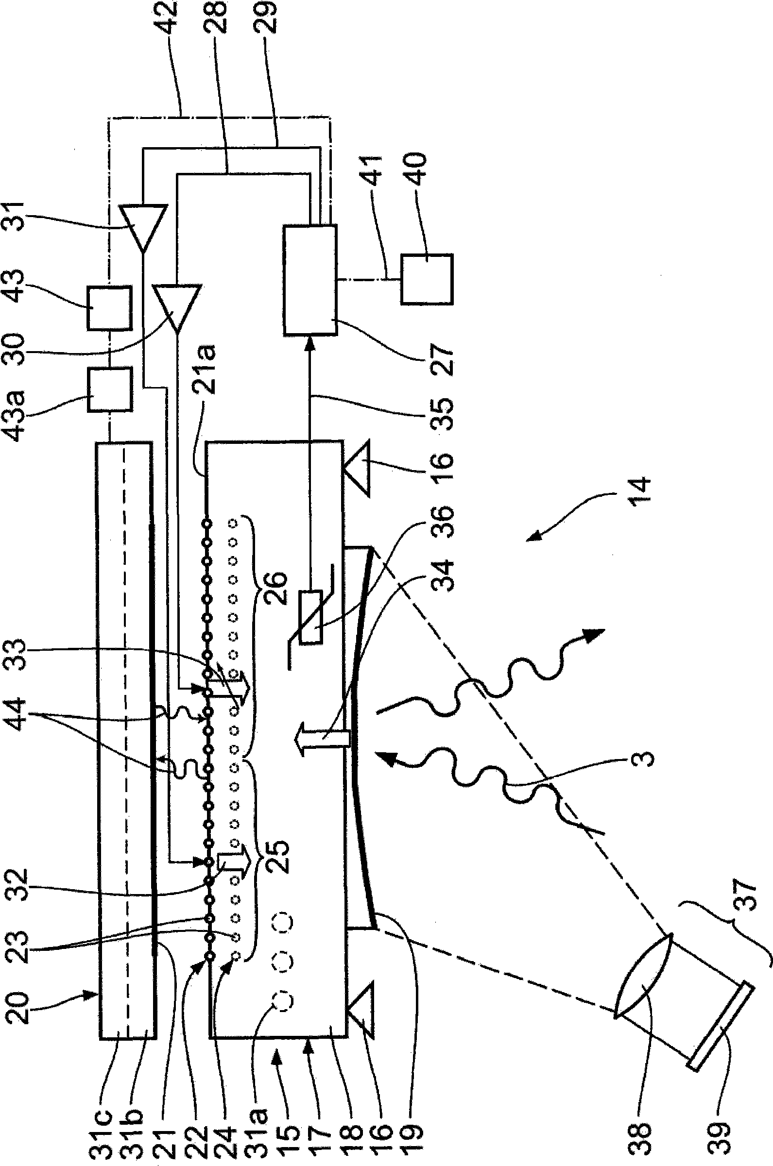
A device serves for controlling temperature of an optical element provided in vacuum atmosphere. The device has a cooling apparatus having a radiational cooling part, arranged apart from the optical element, for cooling the optical element by radiation heat transfer. A controller serves for controlling temperature of the radiational cooling part. Further, the device comprises a heating part for heating the optical element. The heating part is connected to the controller for controlling the temperature of the heating part. The resulting device for controlling temperature in particular can be used with an optical element in a EUV microlithography tool leading to a stable performance of its optics.

Description

technical field [0001] The invention relates to a device for controlling the temperature of an optical element arranged in a vacuum atmosphere. Furthermore, the invention relates to a method for controlling the temperature of an optical element located in a vacuum atmosphere with such a device, an illumination system with such a device for controlling the temperature and a projection optics for microlithography with such a device for controlling the temperature system. Background technique [0002] In certain applications it is important to keep the temperature or temperature profile of the optical mirror arrangement at a given, especially constant level. Examples of such applications are in particular EUV (Extreme Ultra Violet) illumination and projection optics which operate in particular with illumination light wavelengths in the range between 10 nm and 30 nm. These optical systems must operate in ultra-high vacuum environments because EUV photons are absorbed by atmosp...

Claims


Application Information

Patent Timeline
IPC IPC(8): G05D23/19
CPCG03F7/70891G02B5/08G02B5/0891G02B7/008G02B7/1815G03B27/26G03F7/70008G03F7/70825G05D23/1919G21K1/067H01L2924/0002H01L2924/00
Inventor 马库斯·豪夫
Owner CARL ZEISS SMT GMBH
Learn More