A communication line fatigue testing machine

A fatigue testing machine and communication line technology, which is applied in the field of fatigue testing machines, can solve the problems of high power consumption, prolonging the test time, and low power, and achieve the effects of reducing friction loss and vibration, reducing test time, and increasing frequency

Active Publication Date: 2015-12-09
SUZHOU SUXIANG ROBOT INTELLIGENT EQUIP CO LTD
View PDF2 Cites 0 Cited by
  • Summary
  • Abstract
  • Description
  • Claims
  • Application Information

AI Technical Summary

Problems solved by technology

[0003] At present, the fatigue testing machines with a relatively large share in the market mainly include hydraulic servo type, electromagnetic type and mechanical type; among them, the hydraulic servo type fatigue testing machine is a relatively advanced testing device, but the price is high, and the power consumption under low frequency working conditions High cost and high frequency; electromagnetic fatigue testing machine is mainly used for performance testing of materials with better fatigue performance; mechanical fatigue testing machine is suitable for fatigue tests that do not require high frequency, low power and low cost
[0004] But the basic mechanism of the existing mechanical fatigue testing machine is the slider crank mechanism, such as figure 1 As shown, the slider crank mechanism includes a drive gear, a first rotating gear, a connecting rod, a slider and a positioning track, wherein the connecting rod generates a force F on the slider, and the component force of the force F in the horizontal direction makes the slider The block reciprocates in a straight line along the positioning track, but the component force in the vertical direction will act on the positioning tracks on both sides of the slider. Therefore, when the crank slider mechanism performs high-frequency linear reciprocating motion, it will generate severe vibration due to high-frequency frictional resistance; at the same time, due to the existence of friction loss and vibration, it is often necessary to drive the motor A gear reduction device is added between the driving gear and the driving gear, which makes the working frequency of the fatigue testing machine relatively lower and prolongs the test time

Method used


Image

  • A communication line fatigue testing machine
  • A communication line fatigue testing machine
  • A communication line fatigue testing machine

Examples


Embodiment

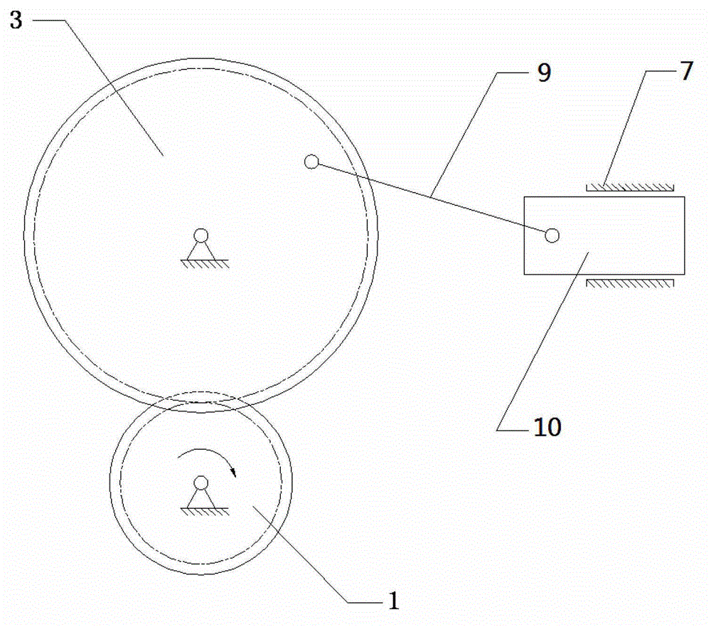
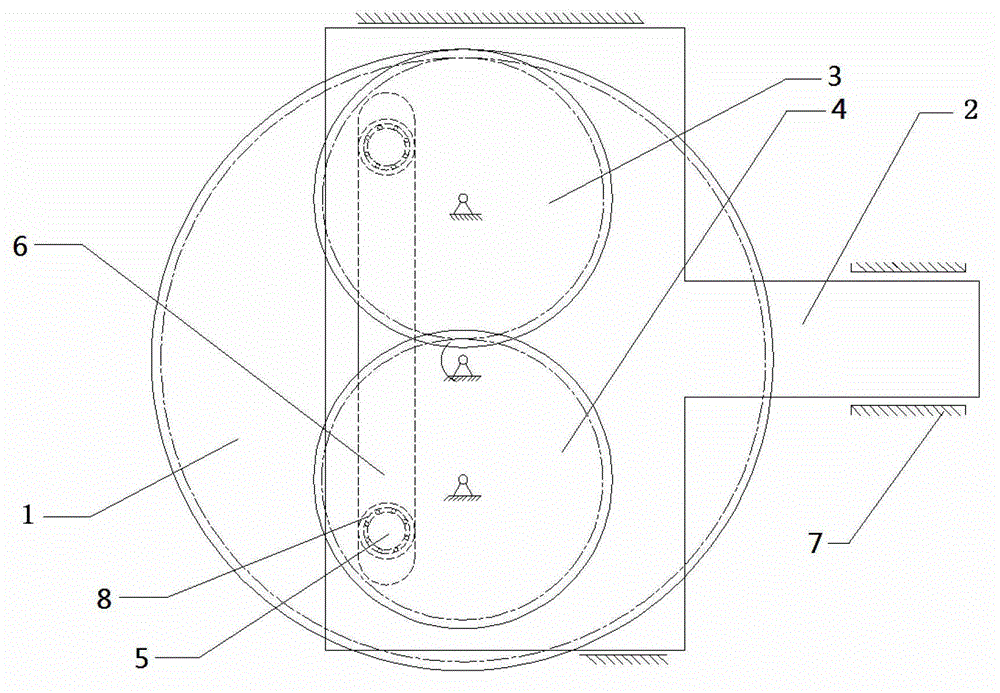
[0020] Example: refer to figure 2 As shown, a communication line fatigue testing machine includes a driving gear 1, an output rod 2, a first rotating gear 3 driven by the driving gear 1 and a second rotating gear 4 driven by the first rotating gear 3; the first rotating gear 3 It rotates synchronously and reversely with the second rotating gear 4 and has the same radius, and drive pins 5 are installed symmetrically on the first rotating gear 3 and the second rotating gear 4 respectively, and the output rod 2 is provided with two driving pins 5 for reverse rotation. To the reciprocating driving track 6, and the driving track 6 is parallel to the line connecting the rotation centers of the first rotating gear 3 and the second rotating gear 4, the two driving pins 5 of the present invention are opposite to the driving track 6 on the output rod 2 To reciprocate, the two drive pins 5 form a pair of reverse friction forces in the direction of the drive track 6, and at the same time...


PUM


Abstract

The invention discloses a fatigue testing machine for a communication wire. The fatigue testing machine is characterized by comprising an output rod and two rotating mechanisms which have the same angular speeds and move in opposite directions, wherein a driving pin is arranged on each of the two rotating mechanisms and the two driving pins are symmetric about a perpendicular bisector of a connection line of two rotating centers of the two rotating mechanisms; a driving rail by which the two driving pins do reverse reciprocating motion is arranged on the output rod and is parallel to the connection line of the two rotating centers. The fatigue testing machine for the communication wire has the advantages that the two driving pins do reverse reciprocating motion along the driving rail on the output rod; a pair of reverse friction is formed by the two driving pins in the direction of the driving rail, and furthermore, a pair of counter-acting forces is formed on the output rod; the two counter-acting forces are counteracted mutually, so that the working force in the vertical direction between the output rod and a positioning rail is theoretically zero, and the positioning rail does not have torque; and therefore, the friction loss and vibration of the output rod in a reciprocating motion process are effectively reduced.

Description

technical field [0001] The invention relates to a fatigue testing machine, in particular to a communication line fatigue testing machine. Background technique [0002] With the rapid development of the economy, the communication industry is advancing rapidly. A series of factors such as the appearance, service life and price of the product comprehensively determine the competitiveness of the product. The built-in data communication lines of notebook computers and mobile phones need repeated bending, while A wire is usually wound by several thin wires, and the outer layer is wrapped with insulating skin. The failure of a single or multiple thin wires inside the communication wire due to high-frequency fatigue damage will have a serious impact on the reliability of signal transmission. Therefore, This type of communication line needs to use a high-frequency fatigue testing machine to perform high-frequency and low-amplitude fatigue life tests to ensure the bending resistance o...

Claims


Application Information

Patent Timeline
Patent Type & Authority Patents(China)
IPC IPC(8): G01N3/34
Inventor 王明娣钟康民周刘蕾黄颖杨宏兵
Owner SUZHOU SUXIANG ROBOT INTELLIGENT EQUIP CO LTD
Why Eureka
Try Eureka